
华为配置专题
华为配置专题
基础配置(送分题):system-view、sysname、interface vlanif、写个IP地址
高频配置(一定要会):VLAN 、DHCP、ACL、策略路由、NAT、静态/默认/RIP/OSPF
偏门的考点(尽力而为):IPv6、4G、WLAN(缺少这个案例)、IPSEC(不全,少了动态配置)
topo下载:华为配置专题案例
基础配置
基础配置视图
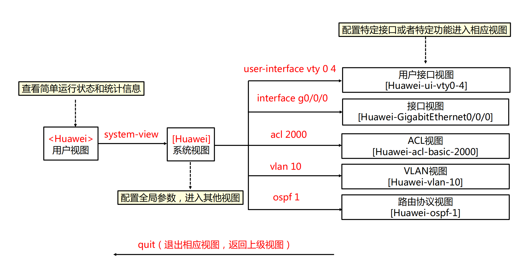
华为登入配置
<AR> system-view //进入系统模式
[AR]sysname Huawei //设备命名为Huawei
[Huawei] telnet server enable //开启设备telnet功能
[Huawei] user-interface vty 0 4 //开启登录端口0-4
[Huawei-ui-vty0-4] protocol inbound telnet //通过telnet协议登录
[Huawei-ui-vty0-4] authentication-mode aaa //认证方式为aaa
[Huawei] aaa //启用aaa
[Huawei-aaa] local-user admin123 password admin123 //配置用户名密码
[Huawei-aaa] local-user admin123 service-type telnet //用户用于telnet
[Huawei-aaa] local-user admin123 privilege level 15 //用户等级为15
[Huawei-aaa] quit //退出来
[Huawei]
VLAN与VLANIF地址配置
<HUAWEI> system-view //进入系统模式
[HUAWEI] sysname Switch //交换机重命名
[Switch] vlan 100 //创建vlan 100(批量创建命令:vlan batch 10 20)
[Switch-vlan100] quit //退出vlan模式
[Switch] interface gigabitethernet 0/0/1 //进入接口
[Switch-GigabitEthernet0/0/1] port link-type access //把交换机接口模式设置为access
[Switch-GigabitEthernet0/0/1] port default vlan 100 //把接口划入vlan100
[Switch-GigabitEthernet0/0/1] quit //退出
[Switch] interface vlanif 100 //进入三层vlanif接口
[Switch-Vlanif100] ip address 172.16.1.1 24 //配置IP地址
[Switch-Vlanif100] quit //退出
[Switch]
DHCP配置命令
<SwitchA> system-view //进入系统模式
[SwitchA] dhcp enable //启用dhcp服务
[SwitchA] ip pool 1 //系统视图下创建IP地址池1
[SwitchA-ip-pool-1] network 10.1.1.0 mask 255.255.255.128 //配置地址池范围
[SwitchA-ip-pool-1] dns-list 10.1.1.1 //配置DNS
[SwitchA-ip-pool-1] gateway-list 10.1.1.1 //配置PC电脑网关
[SwitchA-ip-pool-1] excluded-ip-address 10.1.1.2 //保留IP地址
[SwitchA-ip-pool-1] excluded-ip-address 10.1.1.4 //保留IP地址
[SwitchA-ip-pool-1] lease 10 // 配置租期
[SwitchA-ip-pool-1] quit //退出
配置VLANIF10接口下的客户端从全局地址池ip pool 1中获取IP地址。
[SwitchA] interface vlanif 10 //进入VLAN10接口
[SwitchA-Vlanif10] ip address 10.1.1.254 255.255.255.128 //配置VLAN网关
[SwitchA-Vlanif10] dhcp select global/interface //全局或接口dhcp服务器
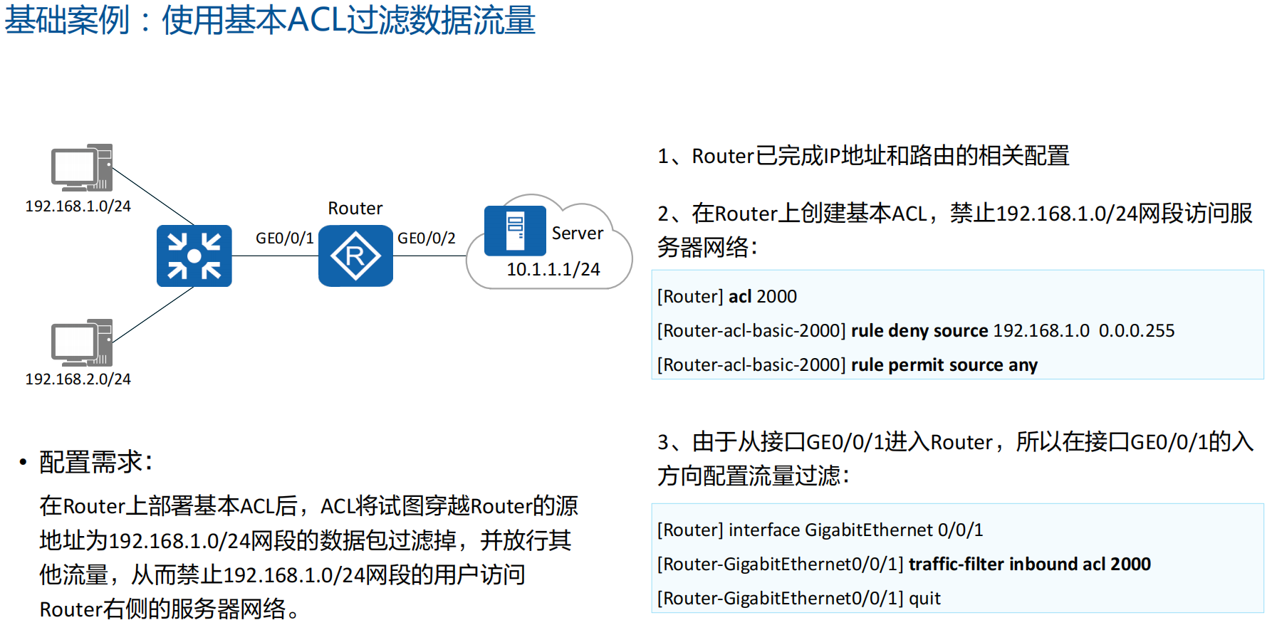
ACL访问控制列表配置
//配置时间段,周一到周五早上8:30到下午18:00
[Huawei] time-range workday 8:30 to 18:00 working-day
//启用编号为2000的ACL
[Huawei] acl 2000
//只允许192.168.1.10这一个用户在工作日可以telnet交换机
[Huawei-acl-basic-2000] rule permit source 192.168.1.10 0 time-range workday
//这个地方rule deny可以不用写,acl在这种场景下最后隐含有一条deny any的语句
[Huawei-acl-basic-2000] rule deny
//进入虚拟接口0-4
[Huawei] user-interface vty 0 4
//应用ACL,只允许匹配acl数据流的的用户telent登陆交换机,没有被permit的全部被deny
[Huawei-ui-vty0-4] acl 2000 inbound
NAT地址转换配置
[Router] nat address-group 1 2.2.2.100 2.2.2.200 //配置NAT地址池1
[Router] nat address-group 2 2.2.2.80 2.2.2.83 //配置NAT地址池2
[Router] acl 2000 //配置ACL2000
//设置ACL200编号为5的规则,允许上述源地址通过
[Router-acl-basic-2000] rule 5 permit source 192.168.20.0 0.0.0.255
[Router-acl-basic-2000] quit
[Router] acl 2001 //配置ACL2001
//设置ACL2001中编号为5的规则,允许上述地址通过
[Router-acl-basic-2001] rule 5 permit source 10.0.0.0 0.0.0.255
[Router-acl-basic-2001] quit
[Router] interface gigabitethernet 3/0/0 //进入接口
//将设置ACL2000匹配的源地址,转换为地址池1的地址,并且不开启端口NAT
[Router-GigabitEthernet3/0/0] nat outbound 2000 address-group 1 no-pat
//将设置ACL2001匹配的源地址,转换为地址池2的地址
[Router-GigabitEthernet3/0/0] nat outbound 2001 address-group 2
[Router-GigabitEthernet3/0/0] quit
[Router]
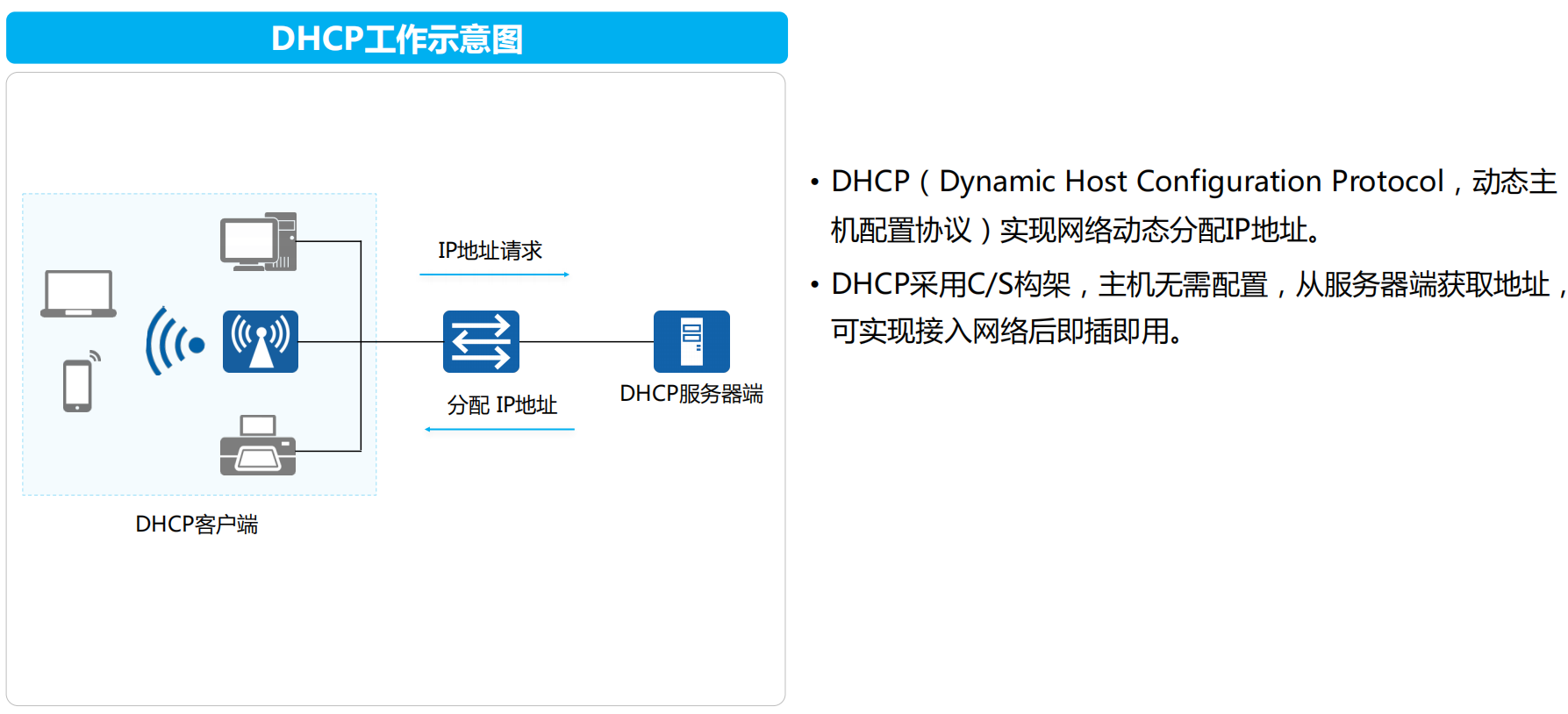
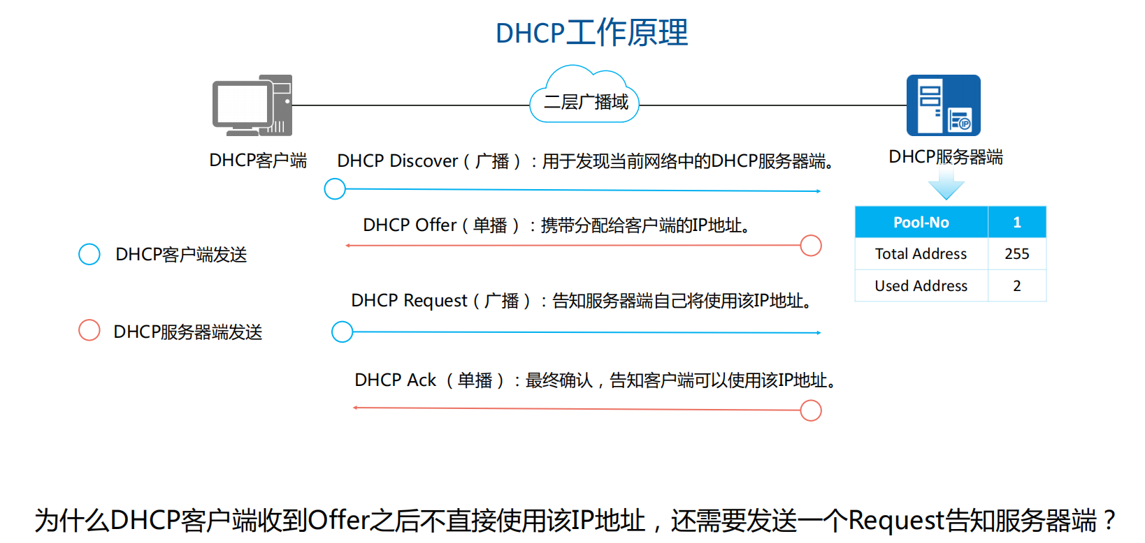
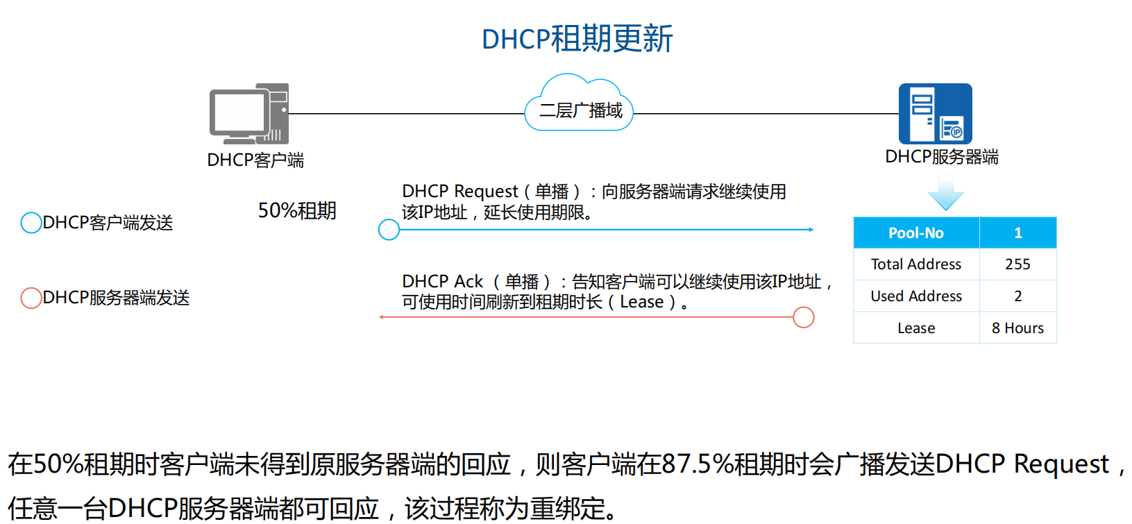
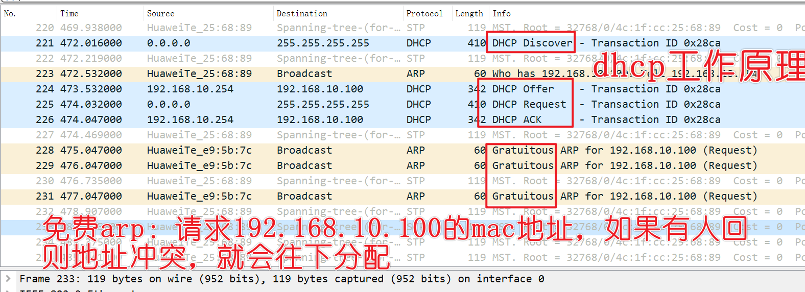
动态主机配置协议 DHCP
DHCP概念和工作原理
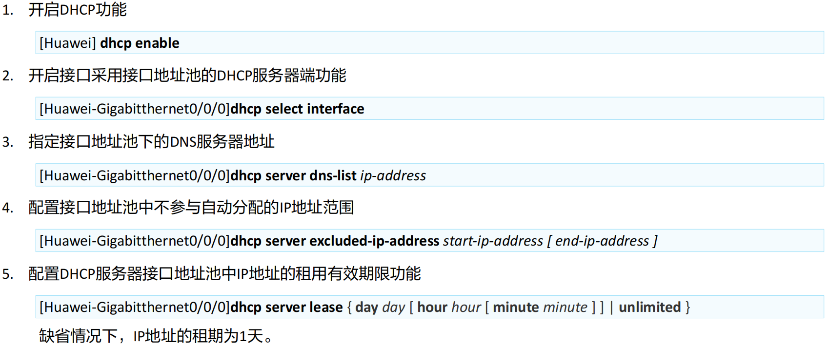
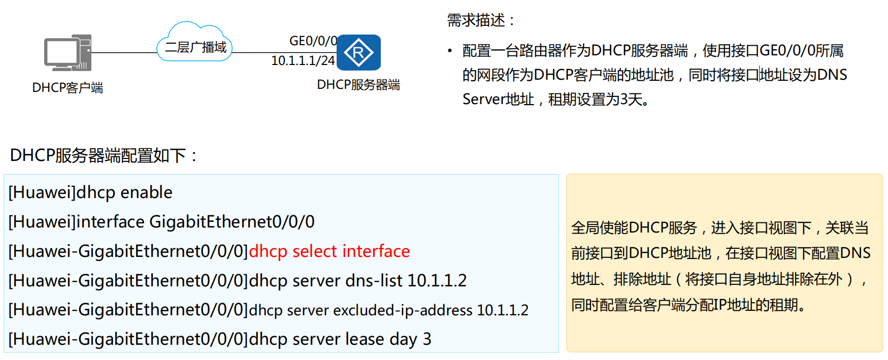
基于接口地址池的DHCP配置
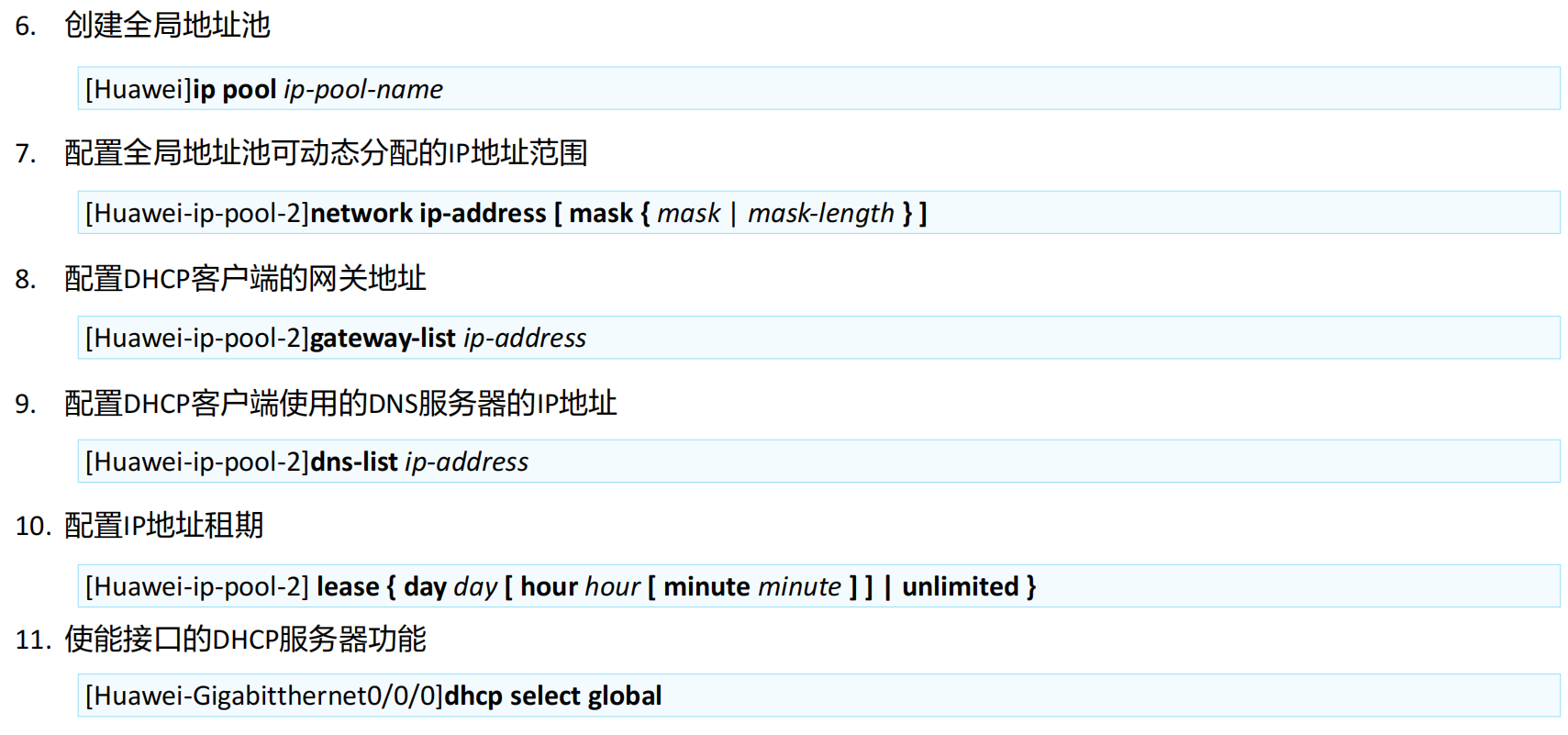
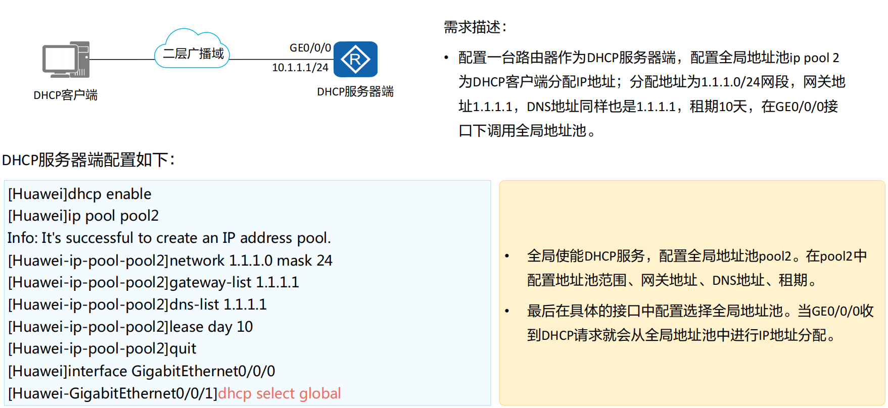
基于全局地址池的DHCP配置
DHCP接口地址池配置案例
DHCP全局地址池配置案例
DHCP案例
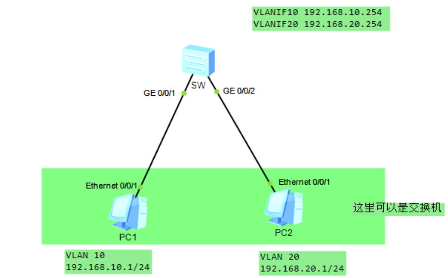
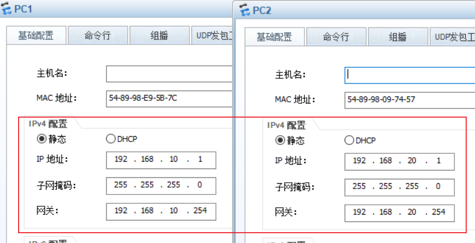
三层交换机跨vlan通信案例
1 | system-view |
DHCP接口和全局配置
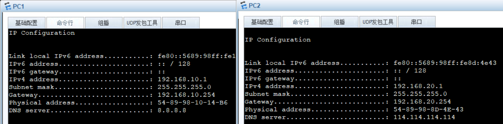
还是上面那个图,左边实现dhcp接口地址池,右边实现全局配置
我们就用SW交换机来做dhcp服务端给下面的客户端分配IP地址
基础vlan配置
1 | system-view |
vlanif10 实现接口dhcp
1 | system-view |
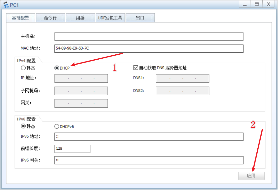
对PC1的E0/0/1接口进行抓包,并且设置dhcp模式并且应用
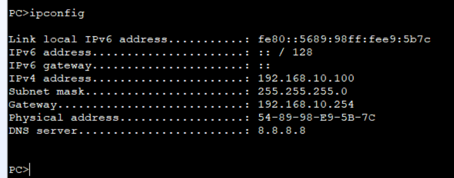
这时候他就可以从可选地址里从大到小分配地址,这是华为才会的,思科则会从小到大进行分配
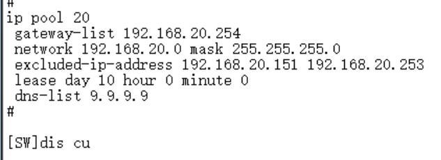
vlanif20 实现全局dhcp
1 | system-view |
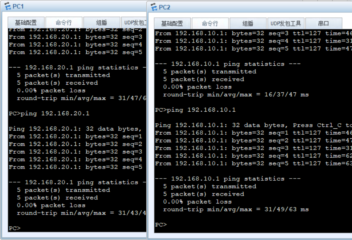
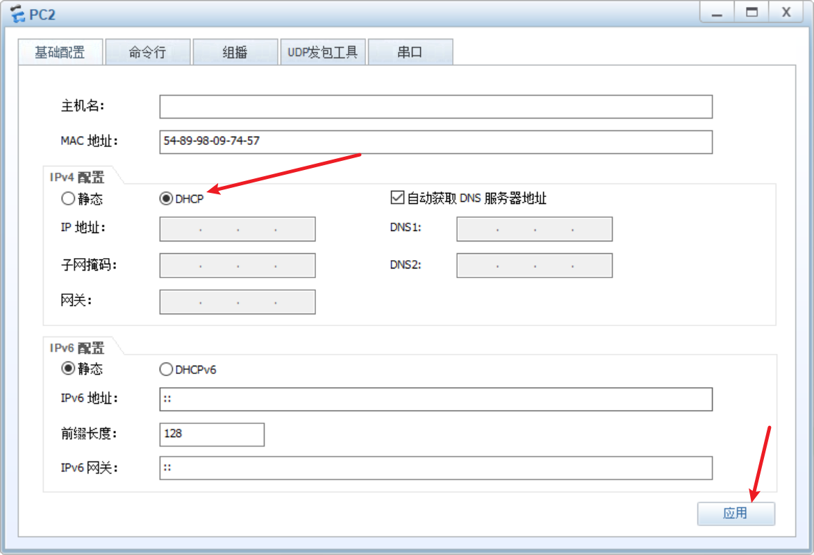
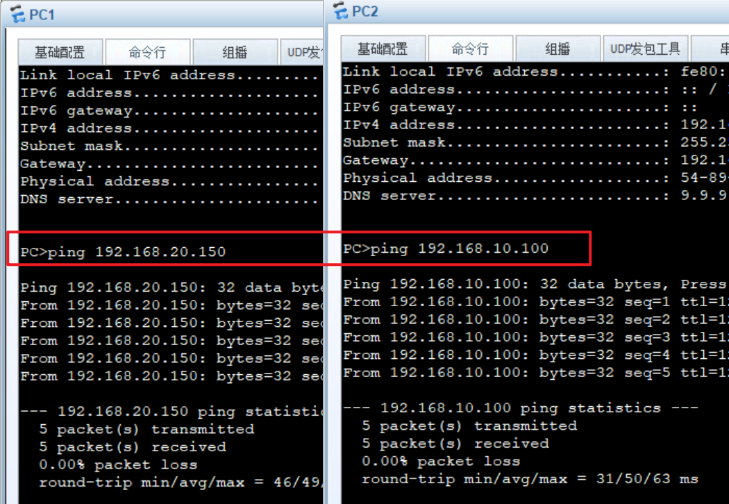
对pc2进行设置自动获取ip模式
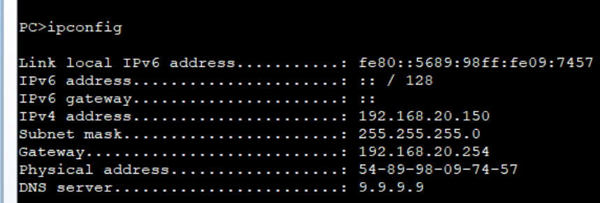
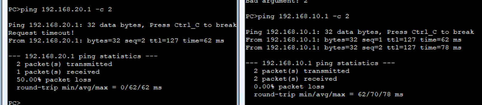
成功,而且两台机子互通
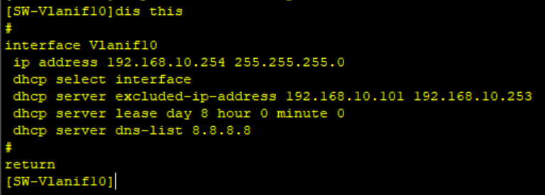
对左边的接口dhcp进行修改成全局dhcp
1 | system-view |
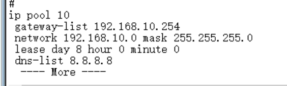
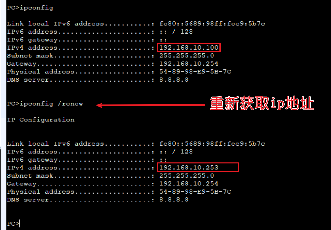
这次我没有排除ip地址,所以他会从这个网段下的所有可用地址进行分配
扩展知识点
7.8.4 Option 43 应用举例
7.8.7 DHCP中继(DHCP Relay)
7.8.8 DHCP Snooping
ACL原理与配置
ACL概述
ACL工作原理
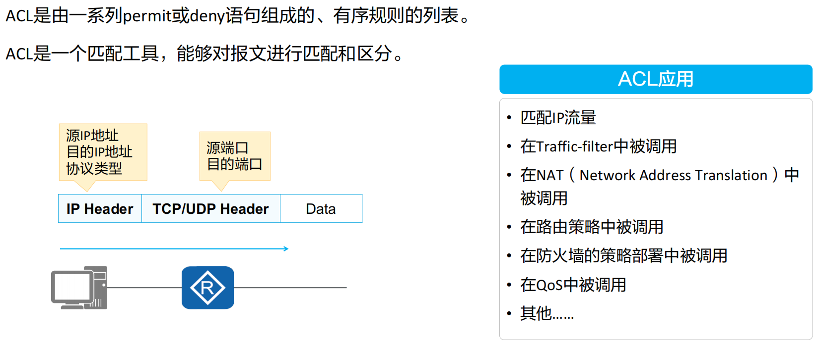
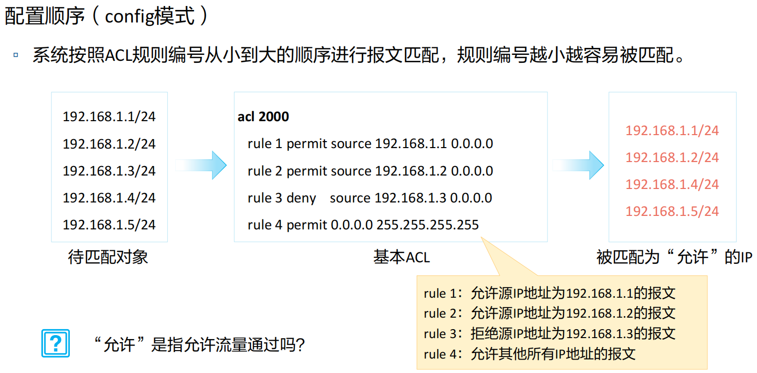
ACL由若干条permit或deny语句组成。
• 每条语句就是该ACL的一条规则,每条语句中的permit或deny就是与这条规则相对应的处理动作。
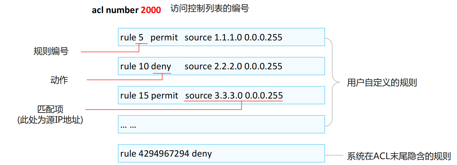
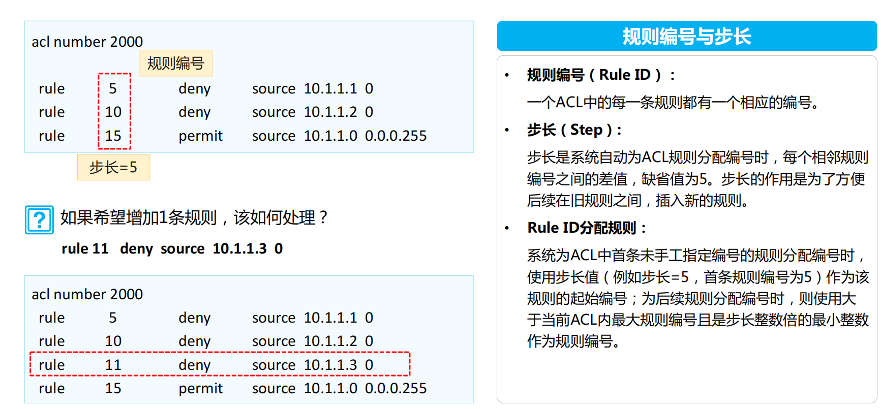
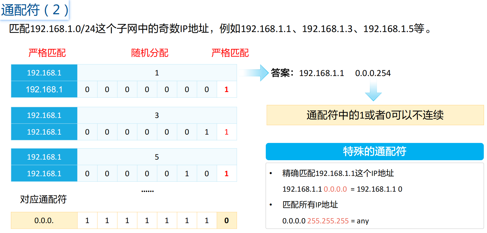
规则编号
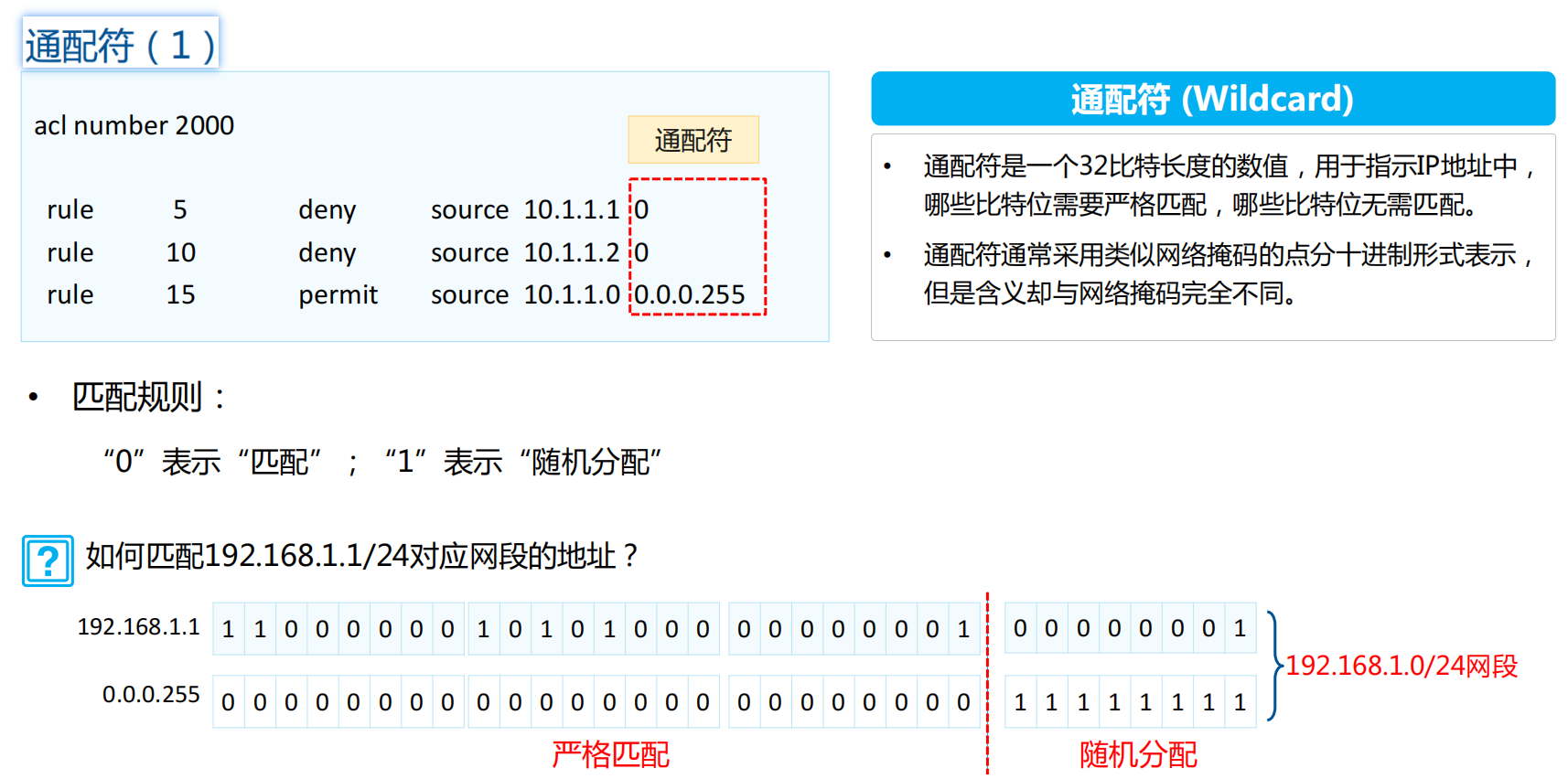
匹配符
ACL分类
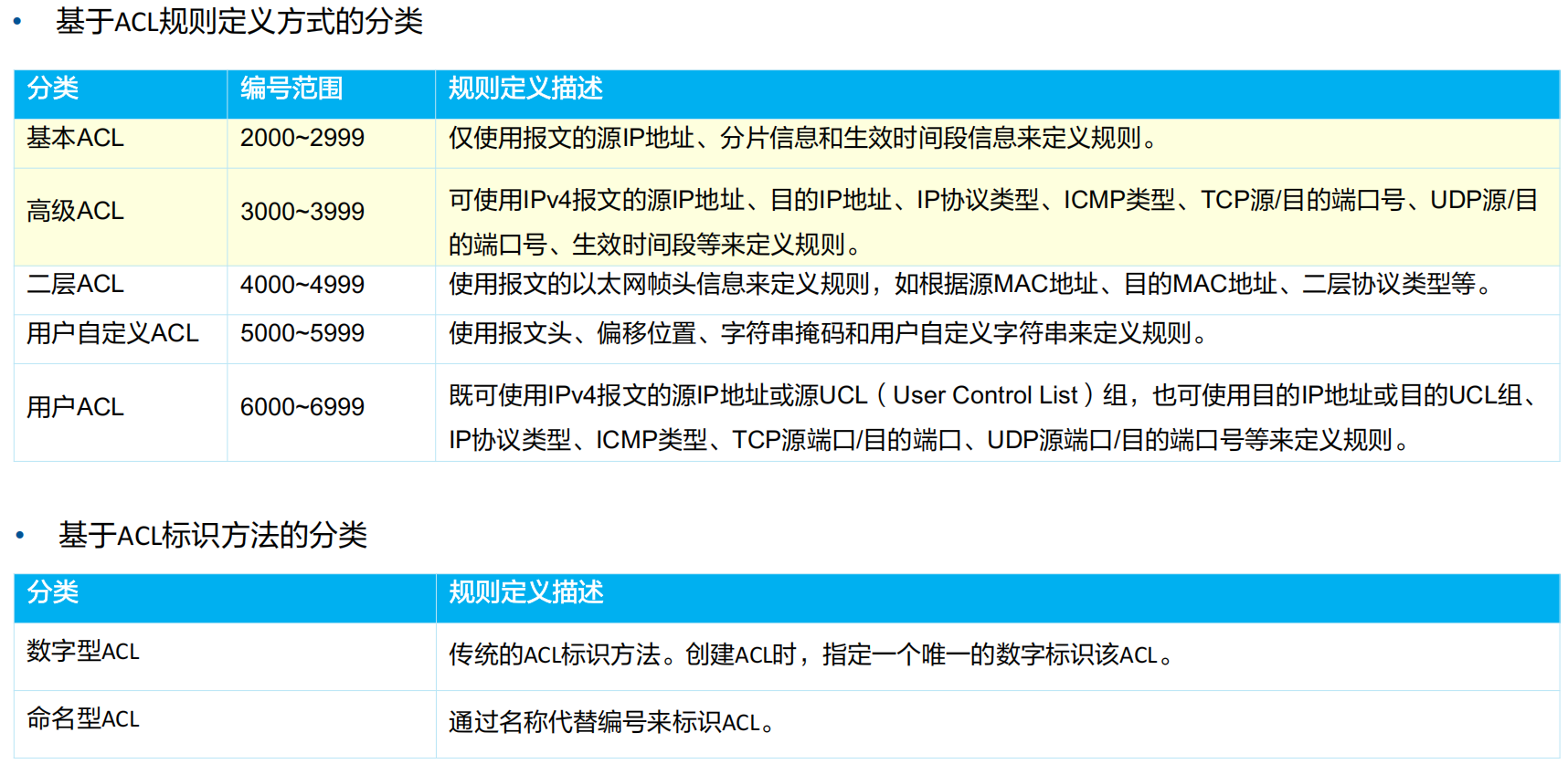
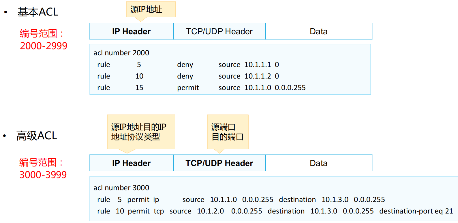
基本ACL和高级ACL
ACL的匹配机制
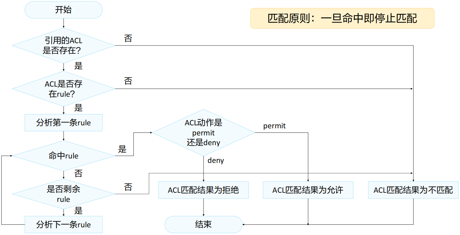
ACL的匹配顺序及匹配结果
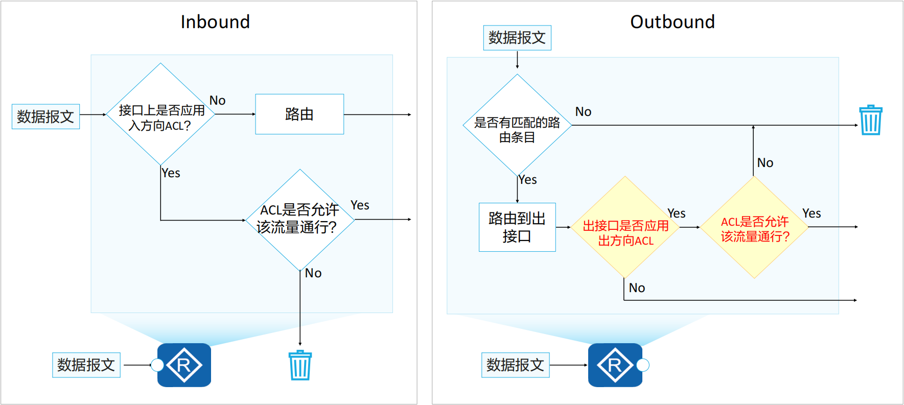
ACL的应用位置
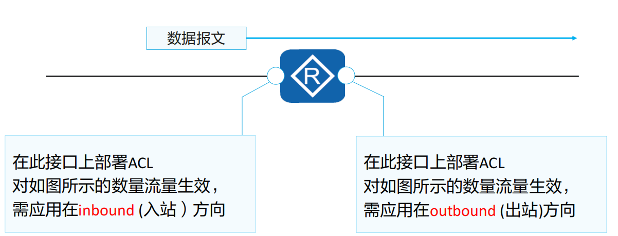
入站 (Inbound)及出站 (Outbound)方向
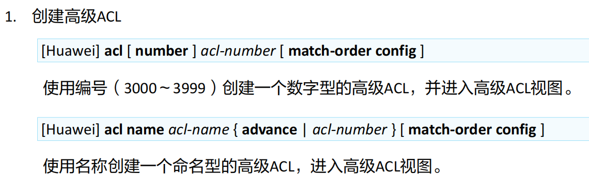
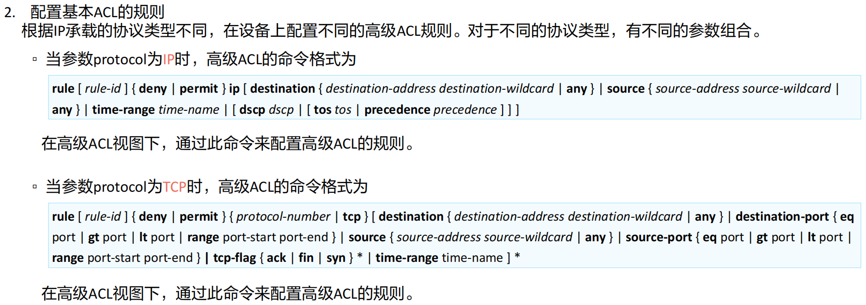
ACL配置及应用
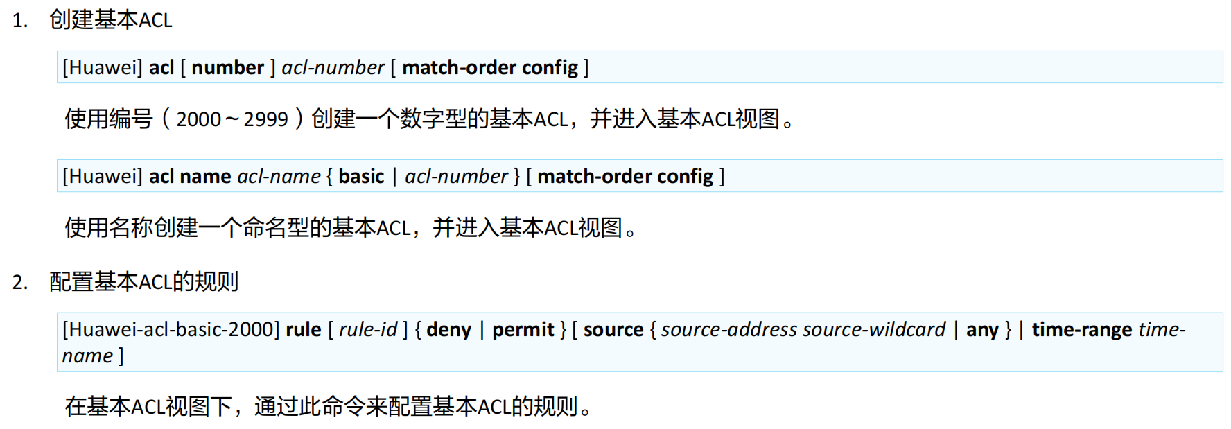
高级ACL命令(1)
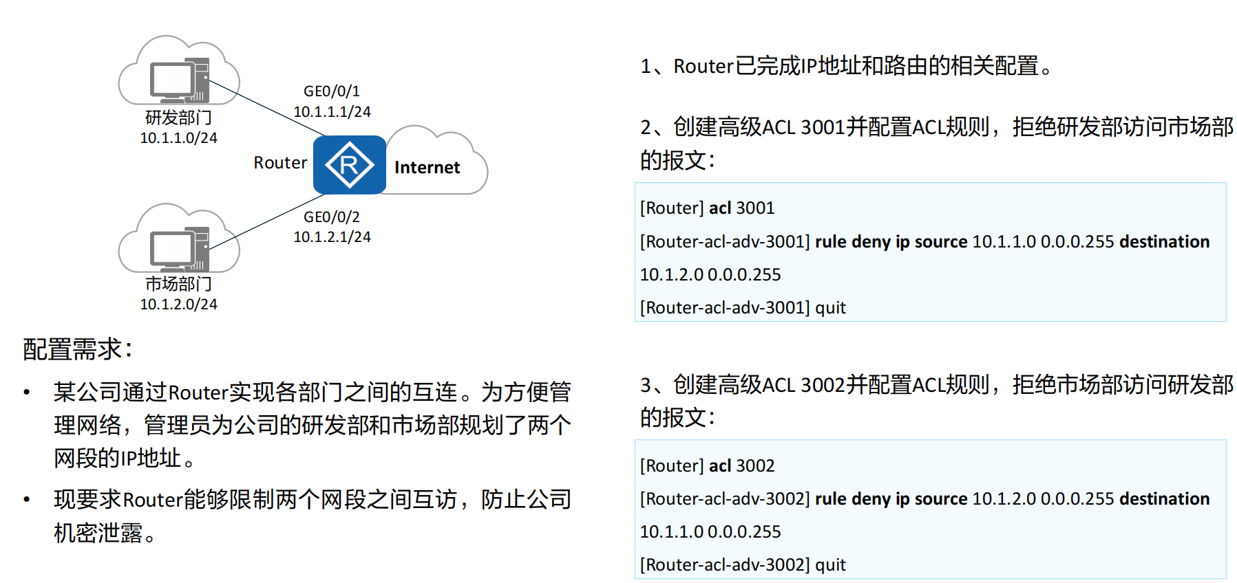
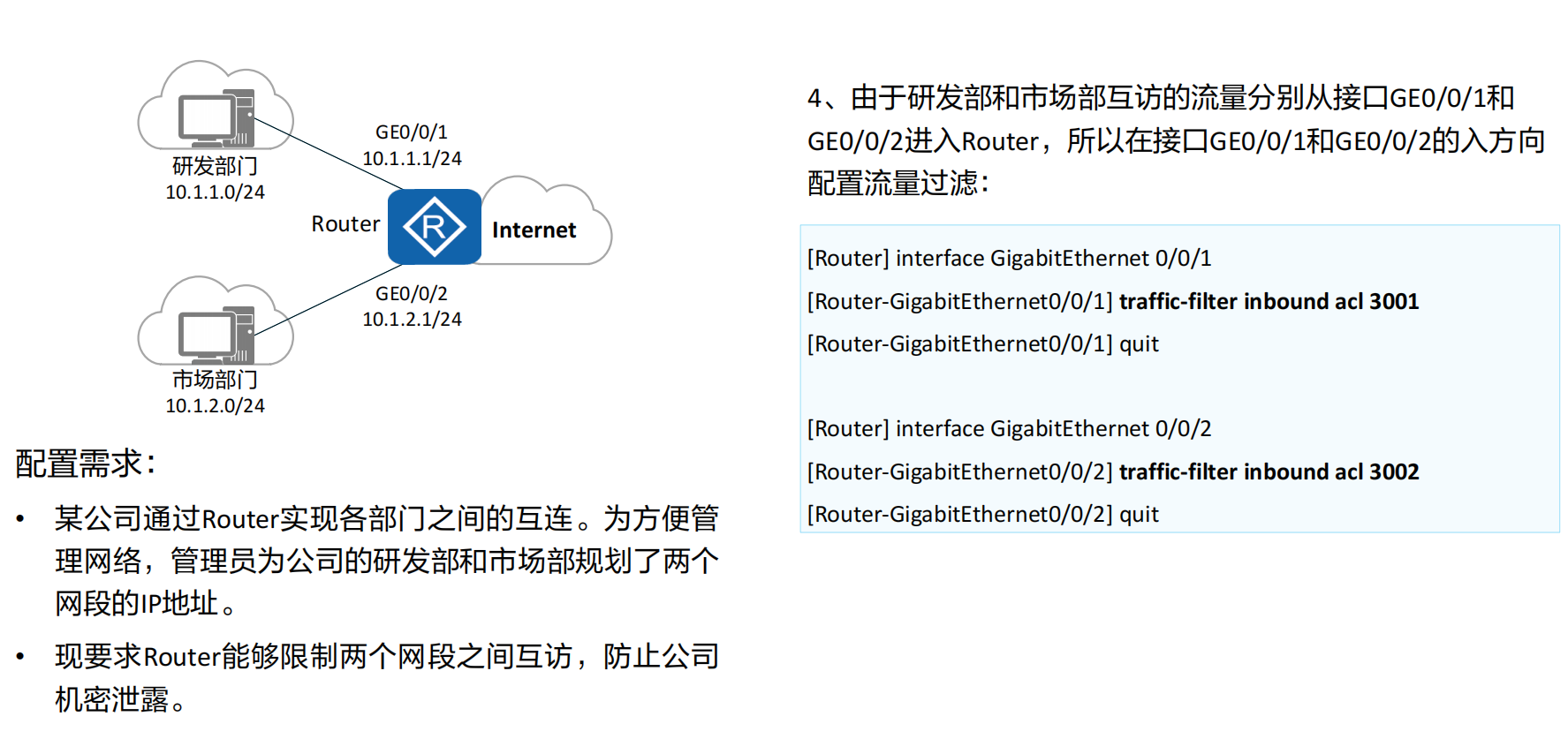
进阶案例:使用高级ACL限制不同网段的用户互访 (1)
1.下列选项中,哪一项才是一条合法的基本ACL的规则?©
A. rule permit ip
B. rule deny ip
C. rule permit source any
D. rule deny tcp source any
2.高级ACL可以基于哪些条件来定义规则?
- 源IP地址
- 目的IP地址
- 源端口号
- 目的端口号
- 协议类型(如TCP、UDP、ICMP等)
- 数据包优先级(DSCP、ToS等)
- ICMP消息类型和代码
- 时间范围(基于时间的ACL)
- 片段标记(非首片分片)
- 数据包长度
- TCP标志位(如SYN、ACK、FIN等)
- VLAN ID
- 源MAC地址
- 目的MAC地址
- 以太网协议类型
章节总结
ACL是一种应用非常广泛的网络技术。它的基本原理是:配置了ACL的网络设备根据事先设定好的报文匹配规则对经过该设备的报文进行匹配,然后对匹配上的报文执行事先设定好的处理动作。这些匹配规则及相应的处理动作是根据具体的网络需求而设定的。处理动作的不同以及匹配规则的多样性,使得ACL可以发挥出各种各样的功效。
ACL技术总是与防火墙、路由策略、QoS、流量过滤等其他技术结合使用。
在本章节中,主要介绍了ACL的相关技术知识,包括:ACL的作用,ACL的组成、匹配和分类、通配符的使用方法,以及ACL的基本配置及应用。
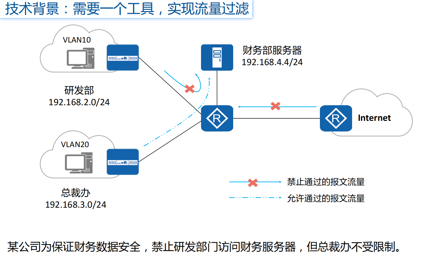
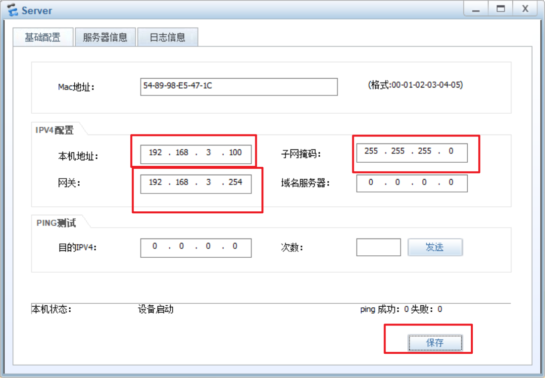
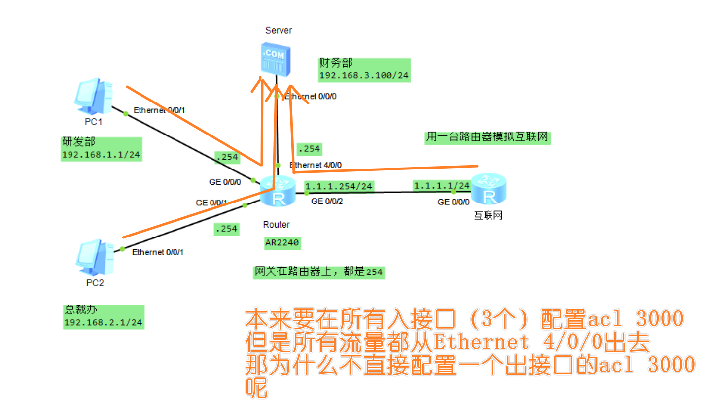
案例
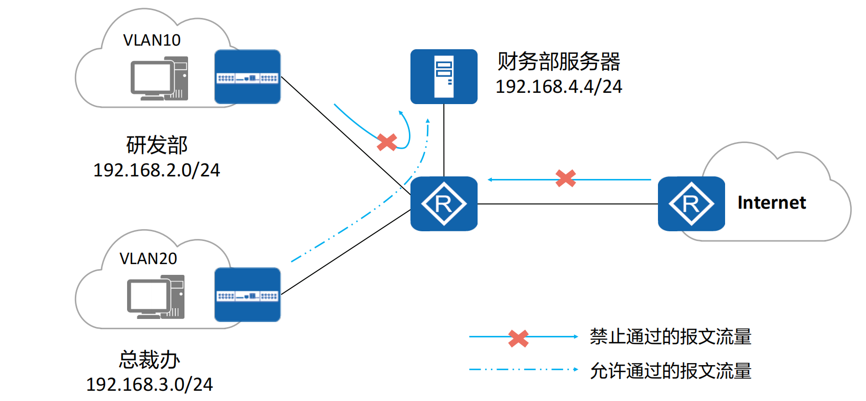
某公司为保证财务数据安全,禁止研发部门访问财务服务器,但总裁办不受限制
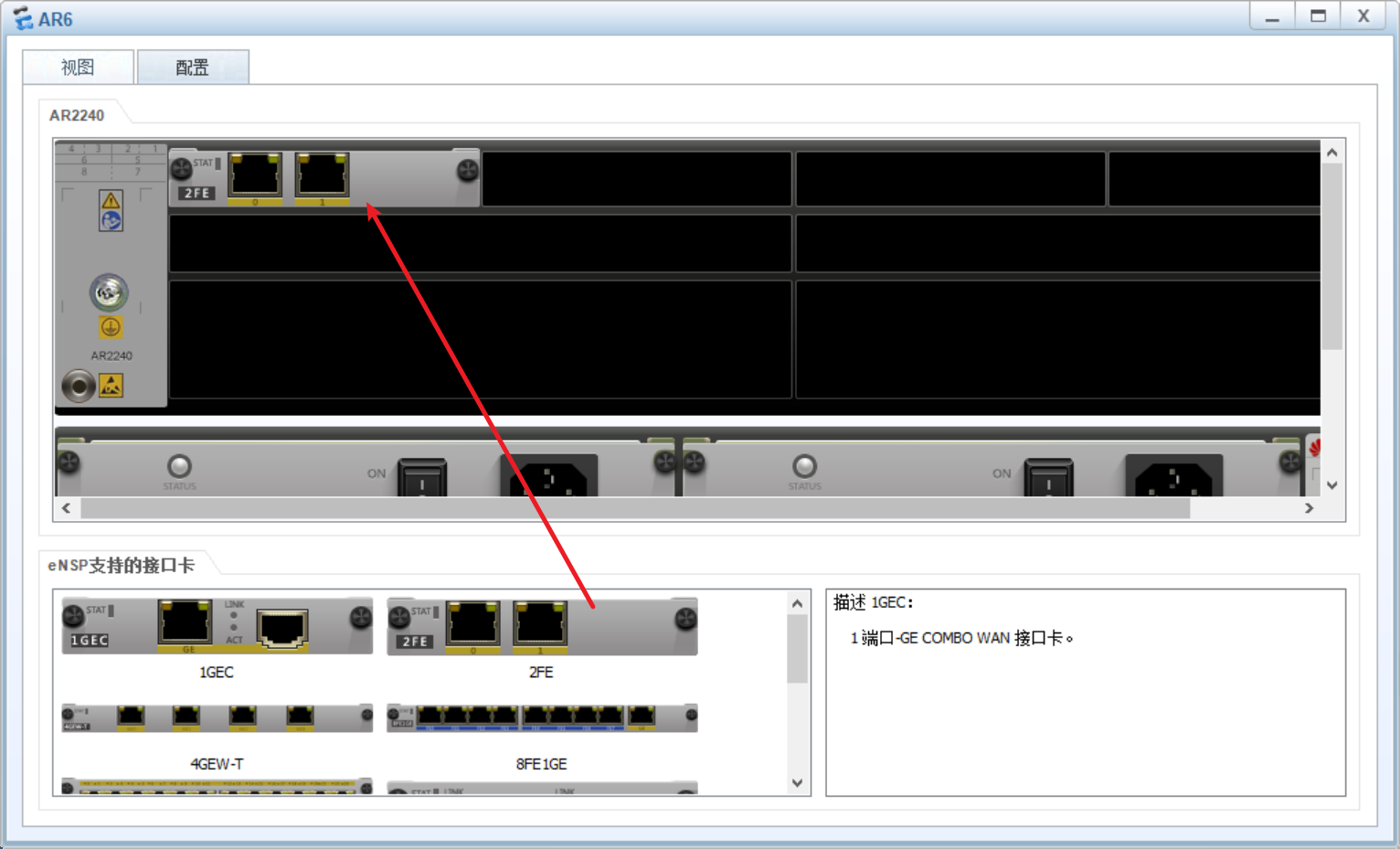
中间的路由器添加了一个百兆网卡接口
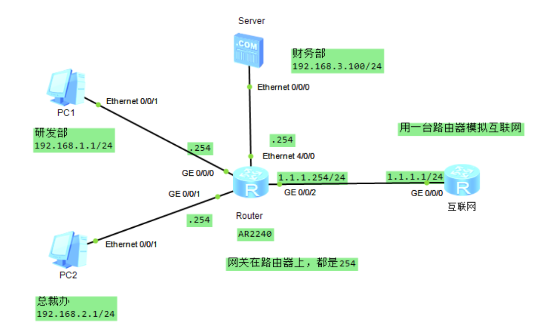
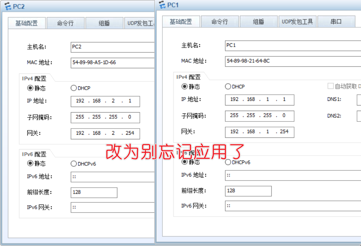
配置路由器各个接口的ip地址
Router
1 | system-view |
互联网
1 | system-view |
为啥ping不通
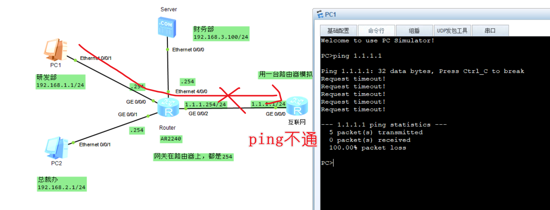
因为pc1的流量可以走到互联网这台路由器,但是回来的流量没有啊,因为互联网这台路由器里没有pc1网段的路由
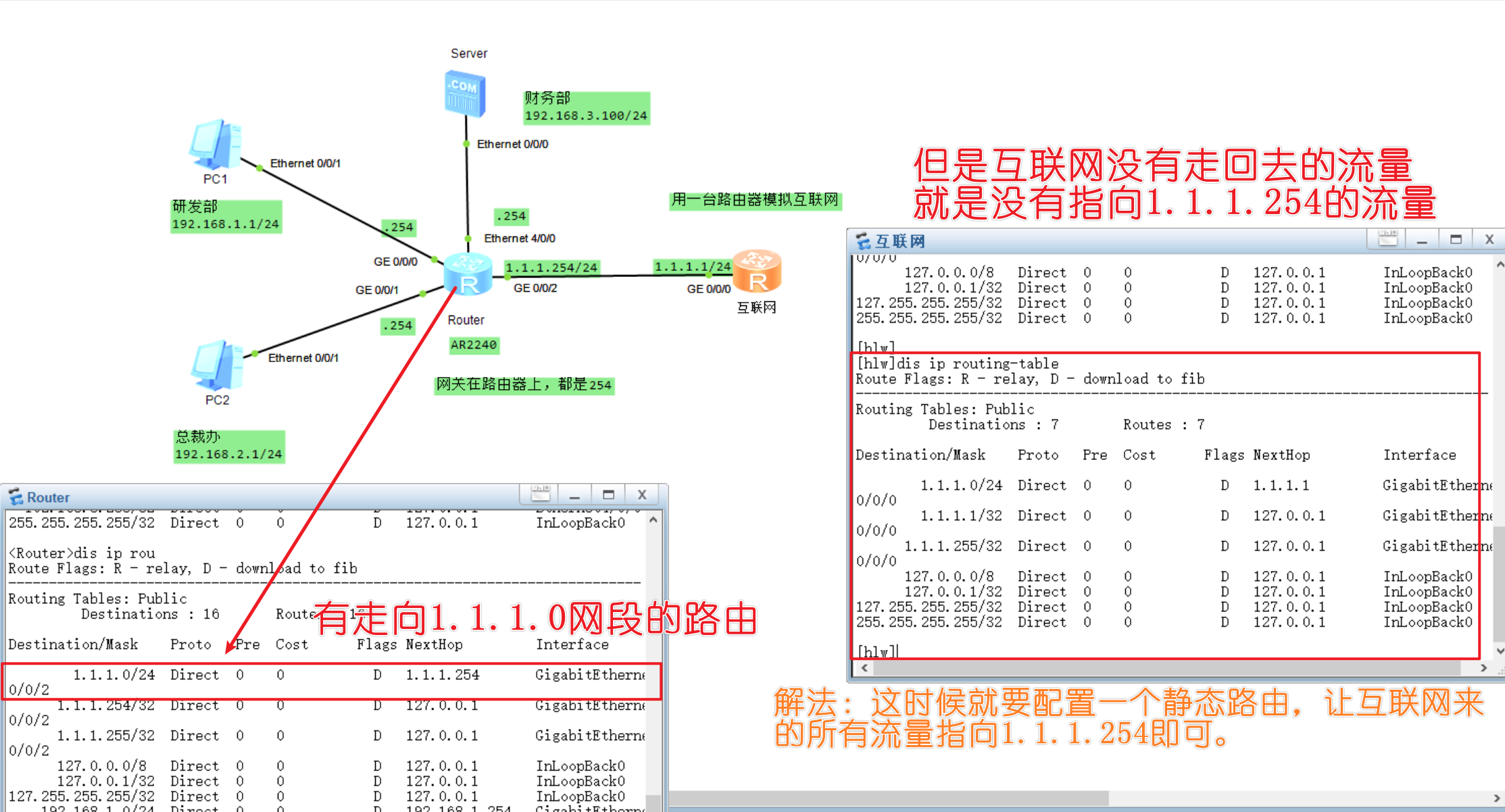
1 | system-view |
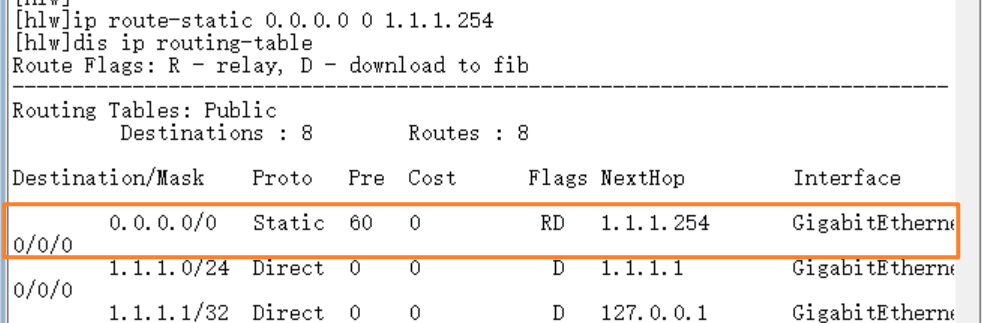
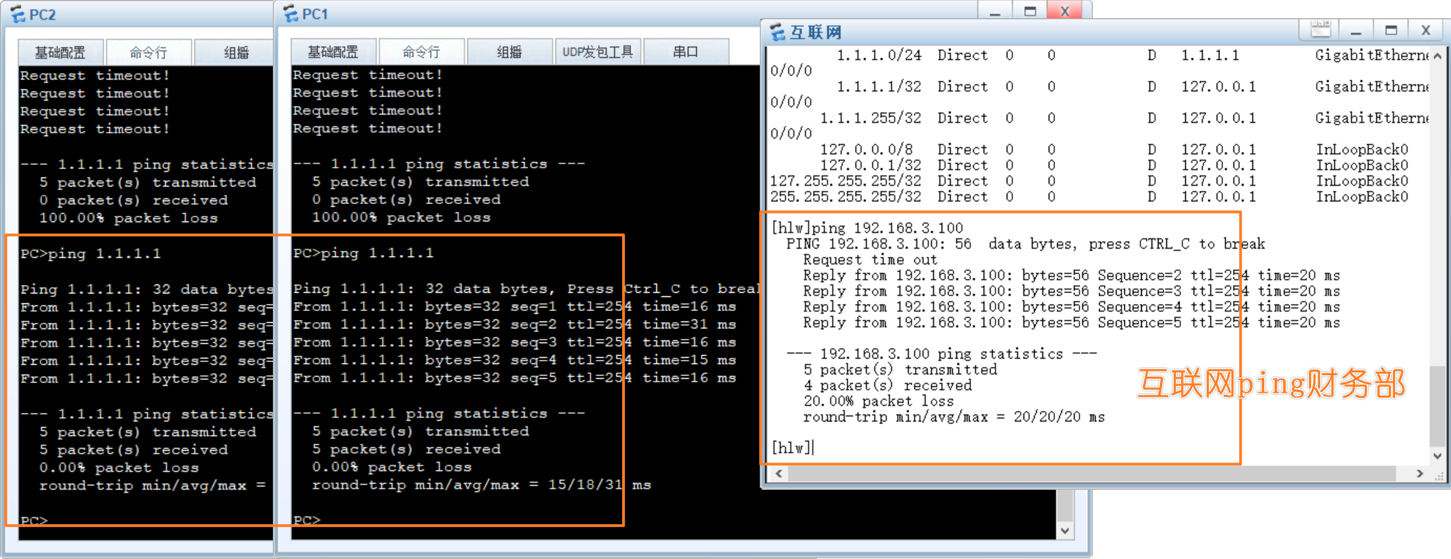
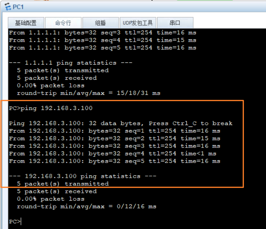
现在所有网络都通了,接下来要配置acl实现访问策略了
某公司为保证财务数据安全,禁止研发部门访问财务服务器,但总裁办不受限制
Router
1 | system-view |
配置完后测试一下PC1能不能访问财务部
还能访问为什么,因为你的acl还没有应用到接口上
Router
1 | system-view |
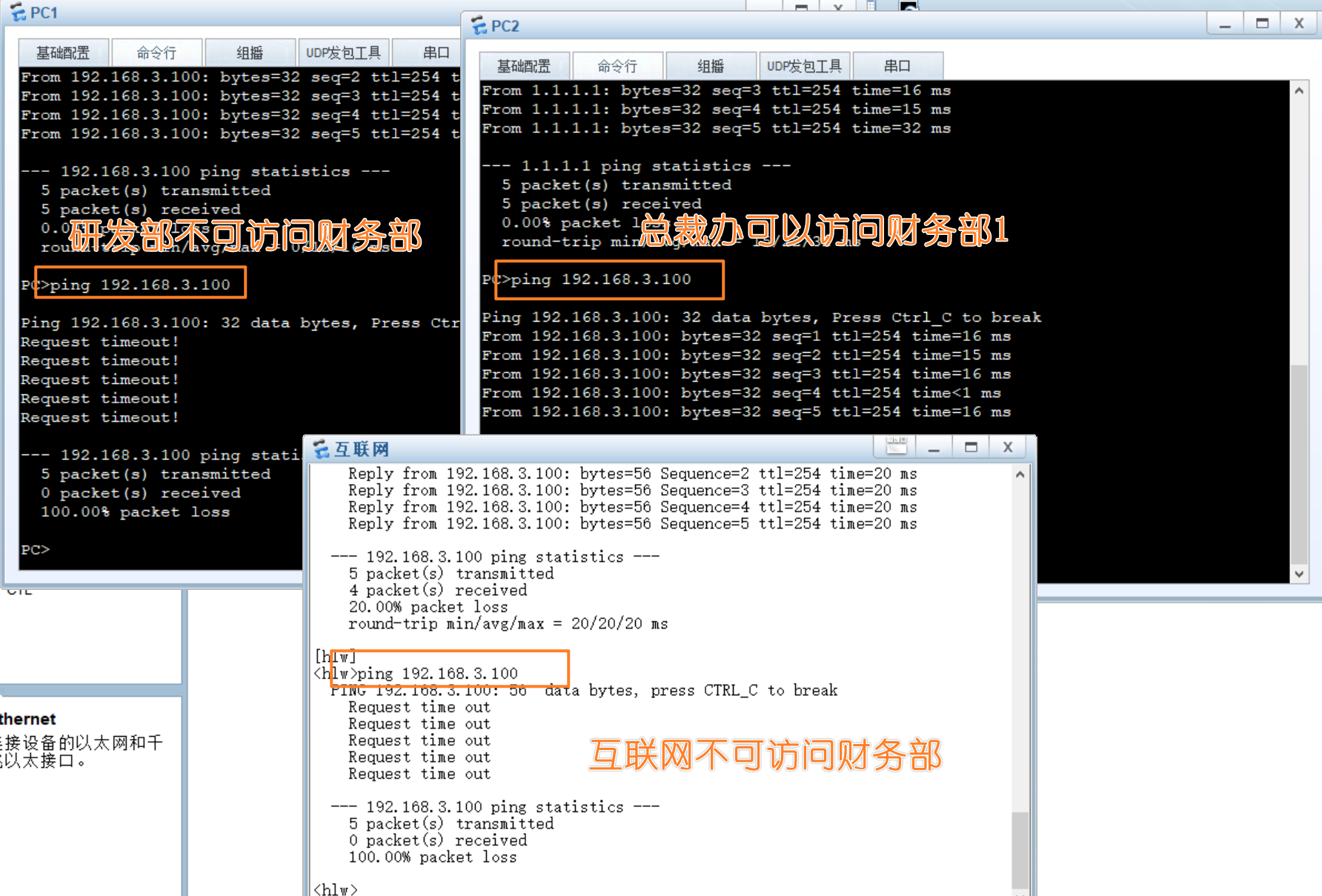
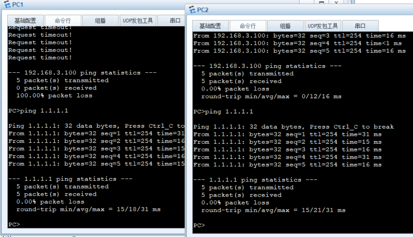
目的达成,且两台pc访问互联网是没有影响的
网络地址转换NAT
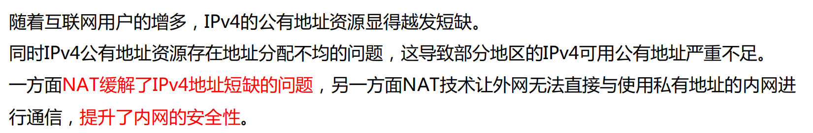
技术背景
随着Internet的发展和网络应用的增多,有限的IPv4公有地址已经成为制约网络发展的瓶颈。为解决
这个问题,NAT(Network Address Translation,网络地址转换)技术应需而生。
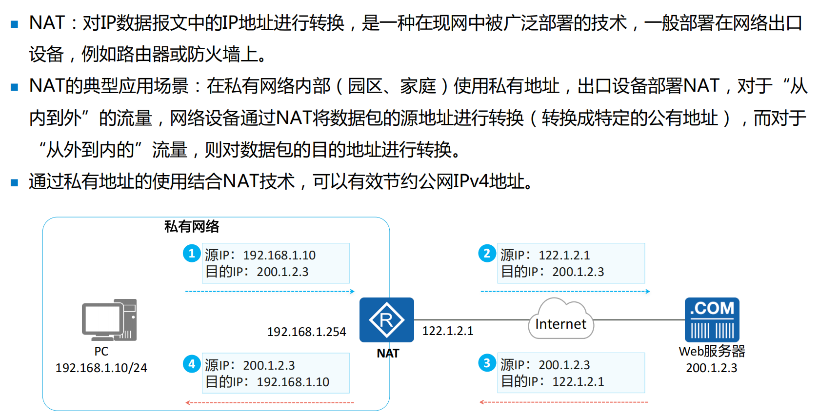
NAT技术主要用于实现内部网络的主机访问外部网络。
本章节我们将了解NAT的技术背景, 学习不同类型NAT的技术原理、使用场景。
NAT概述
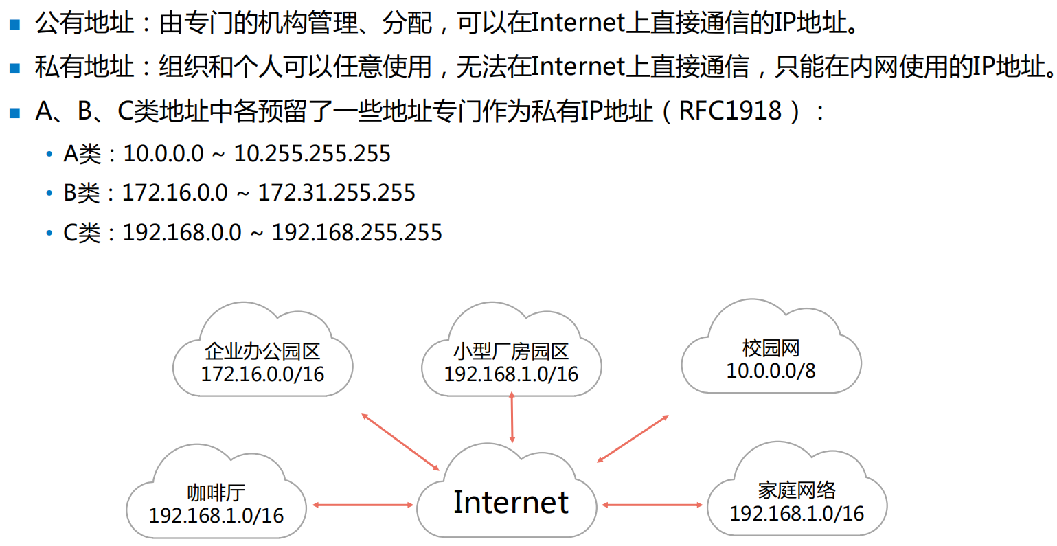
私有IP地址
NAT技术原理
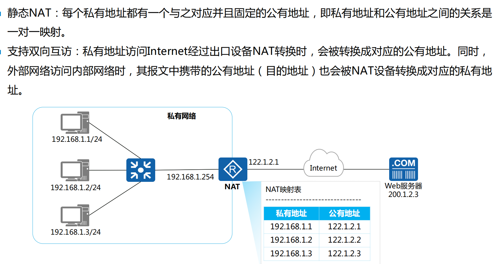
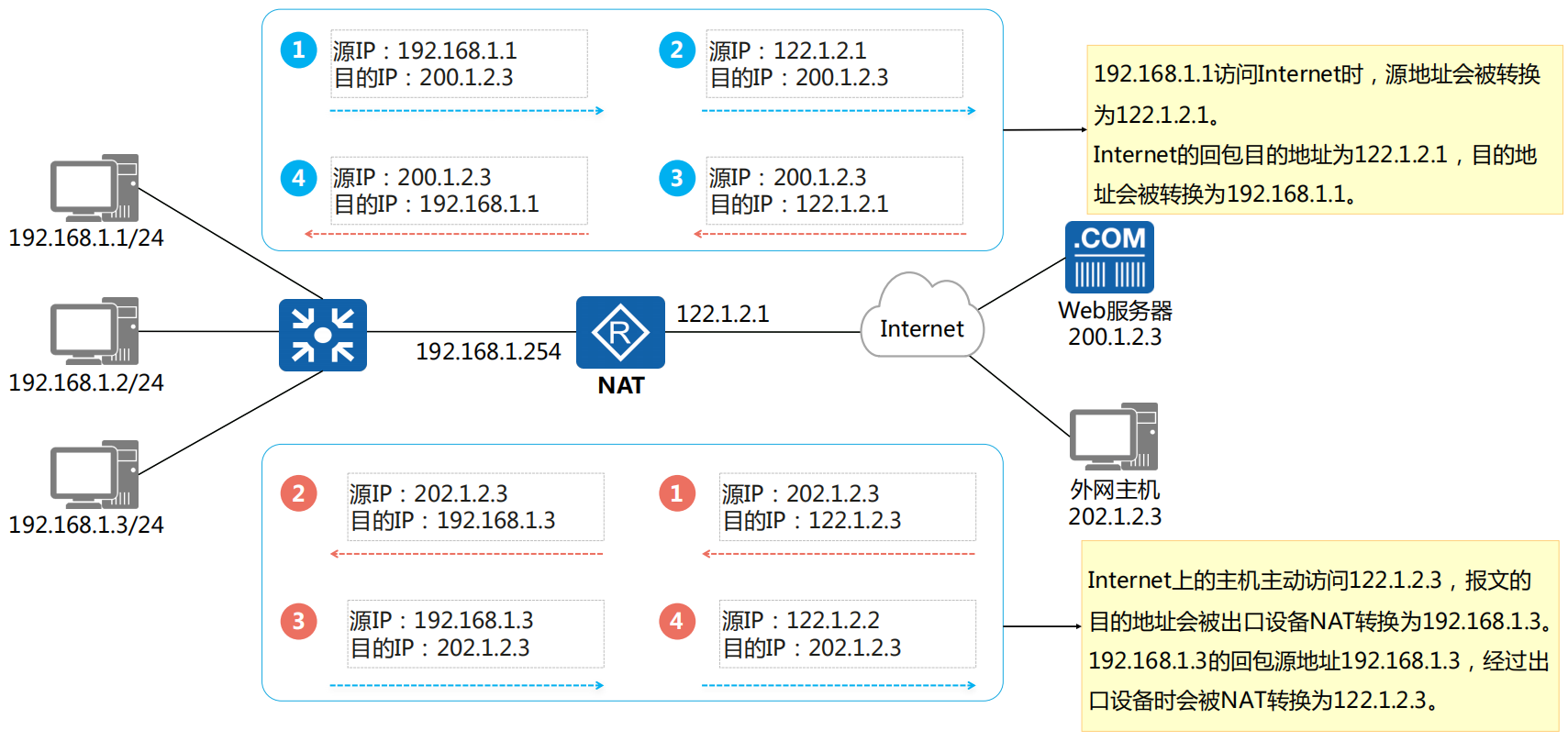
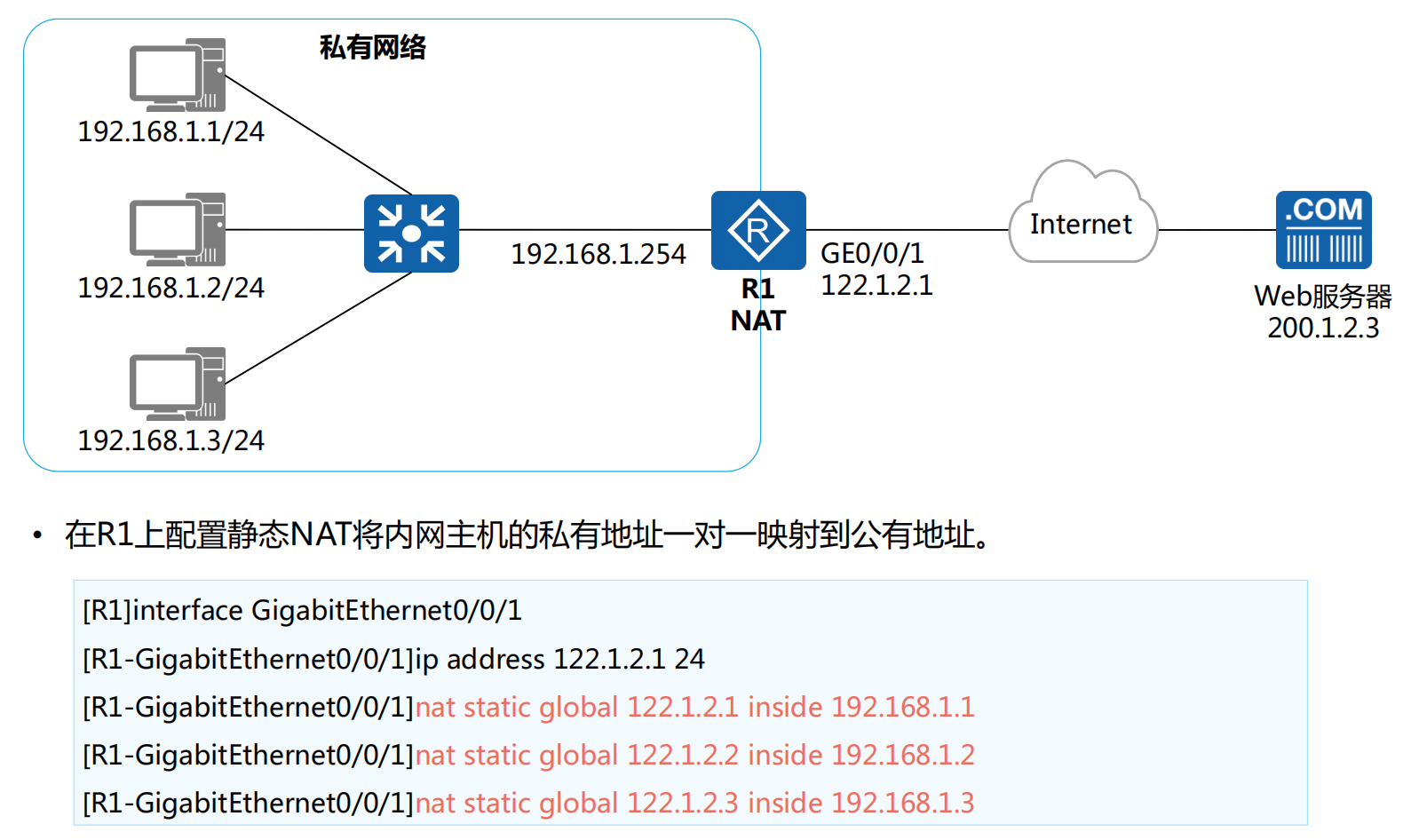
静态NAT
静态NAT原理
静态NAT转换示例
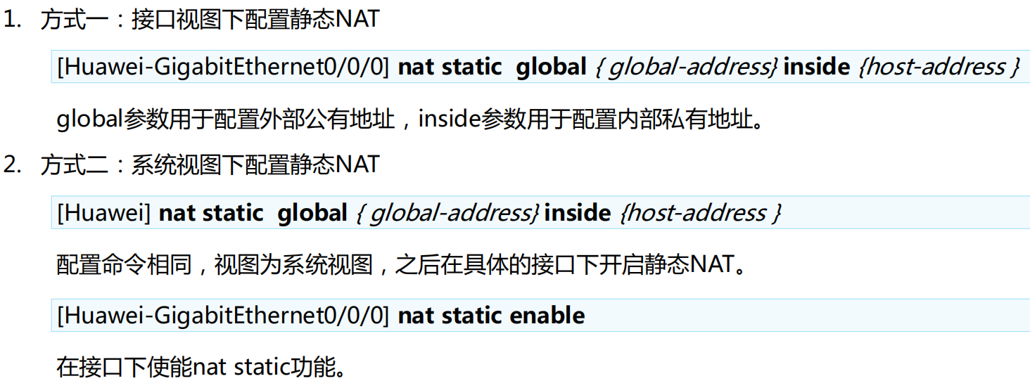
静态NAT配置介绍
静态NAT配置示例
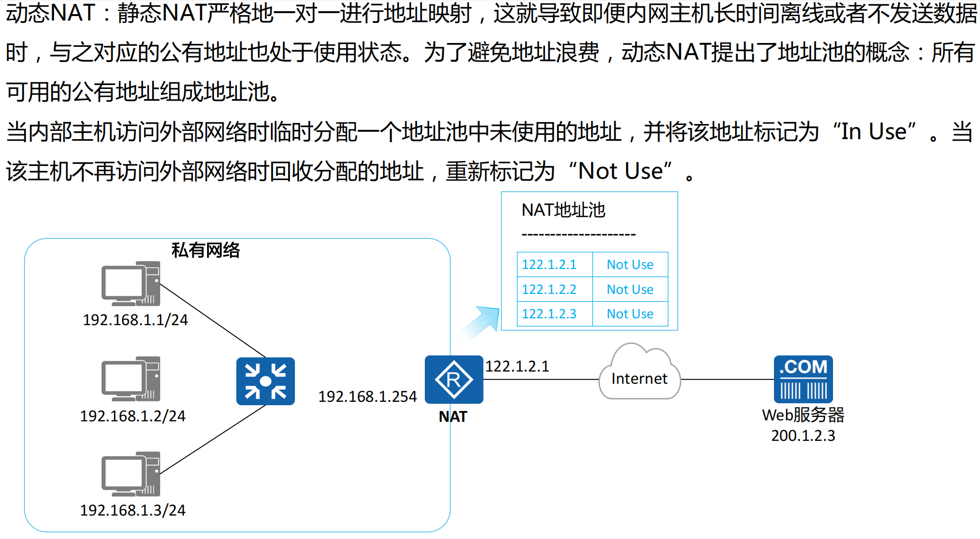
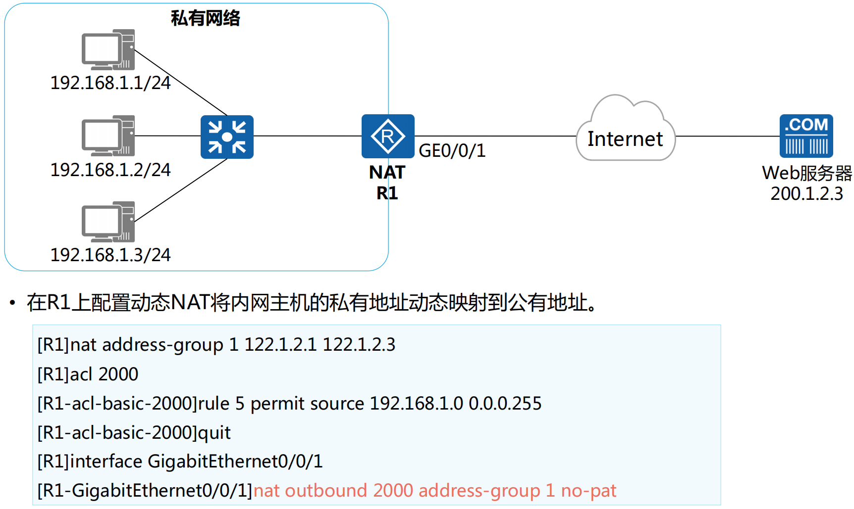
动态NAT
动态NAT原理
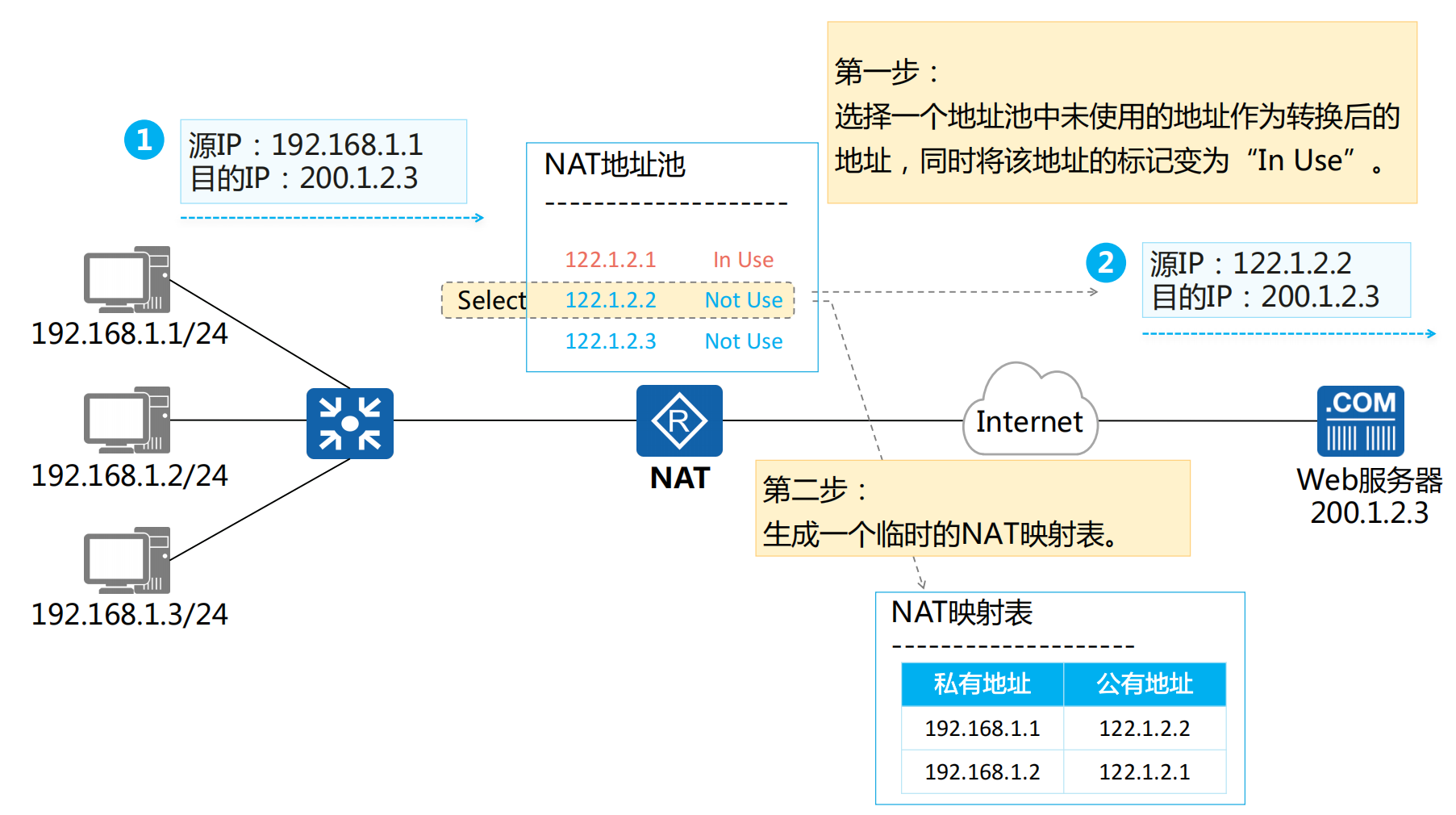
动态NAT转换示例 (出去流量)
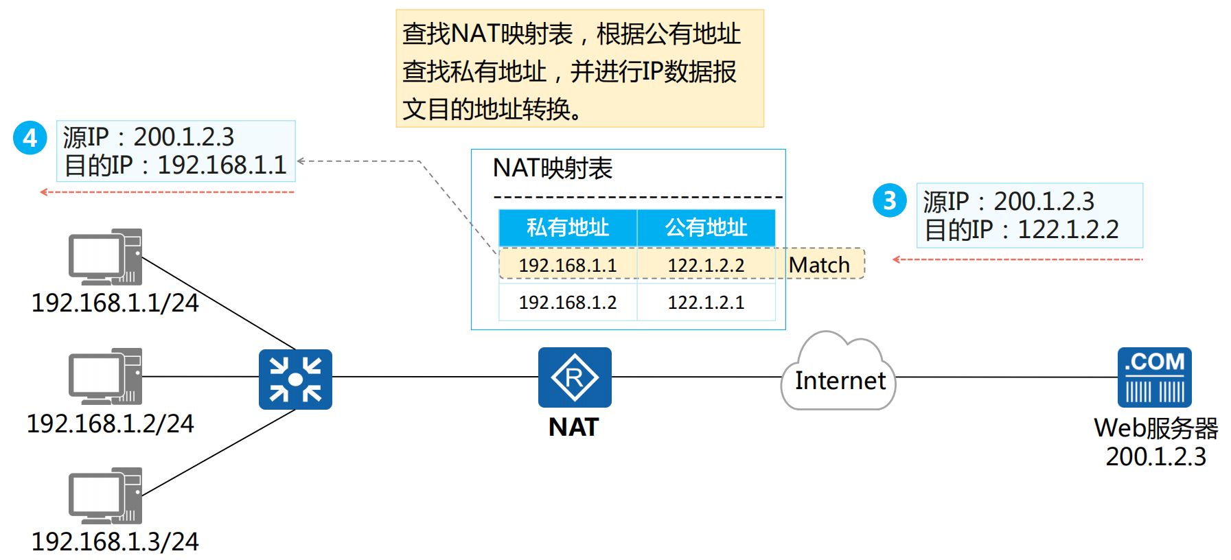
动态NAT转换示例 (回程流量)
动态NAT配置介绍

动态NAT配置示例
NAPT、Easy-IP
NAPT原理
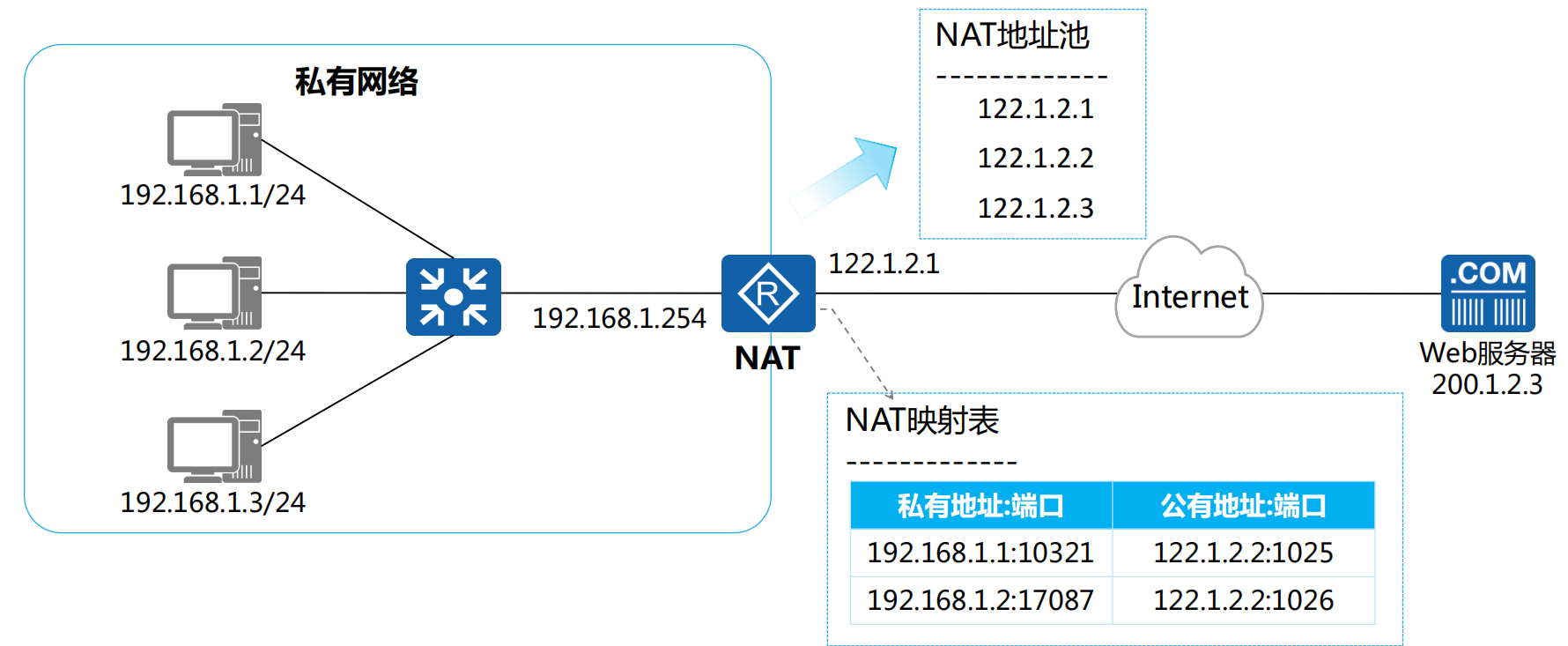
NAPT转换示例 (出去流量)
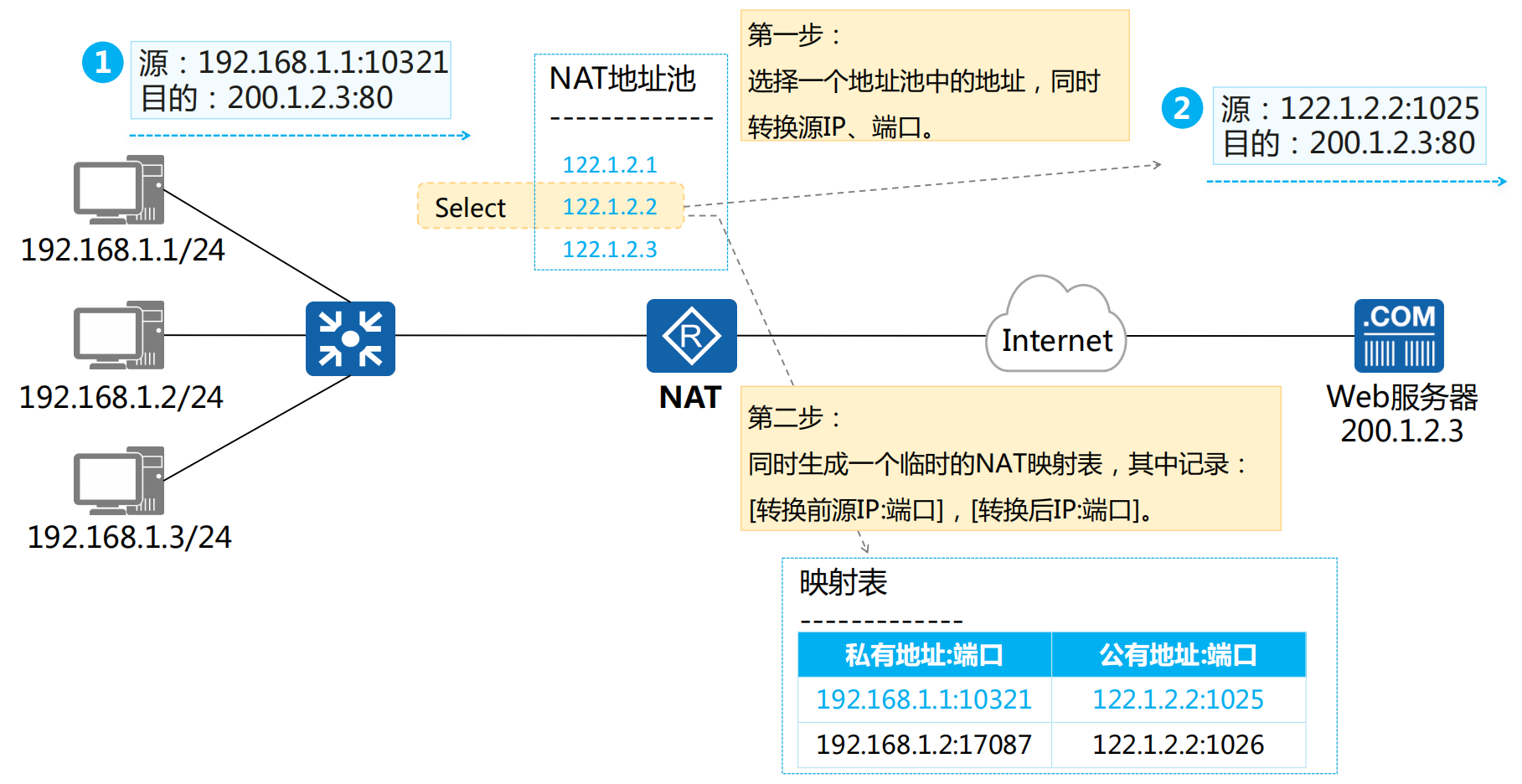
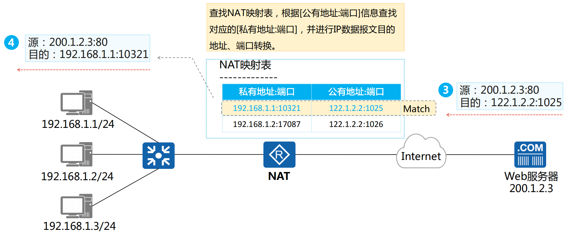
NAPT转换示例 (回程流量)
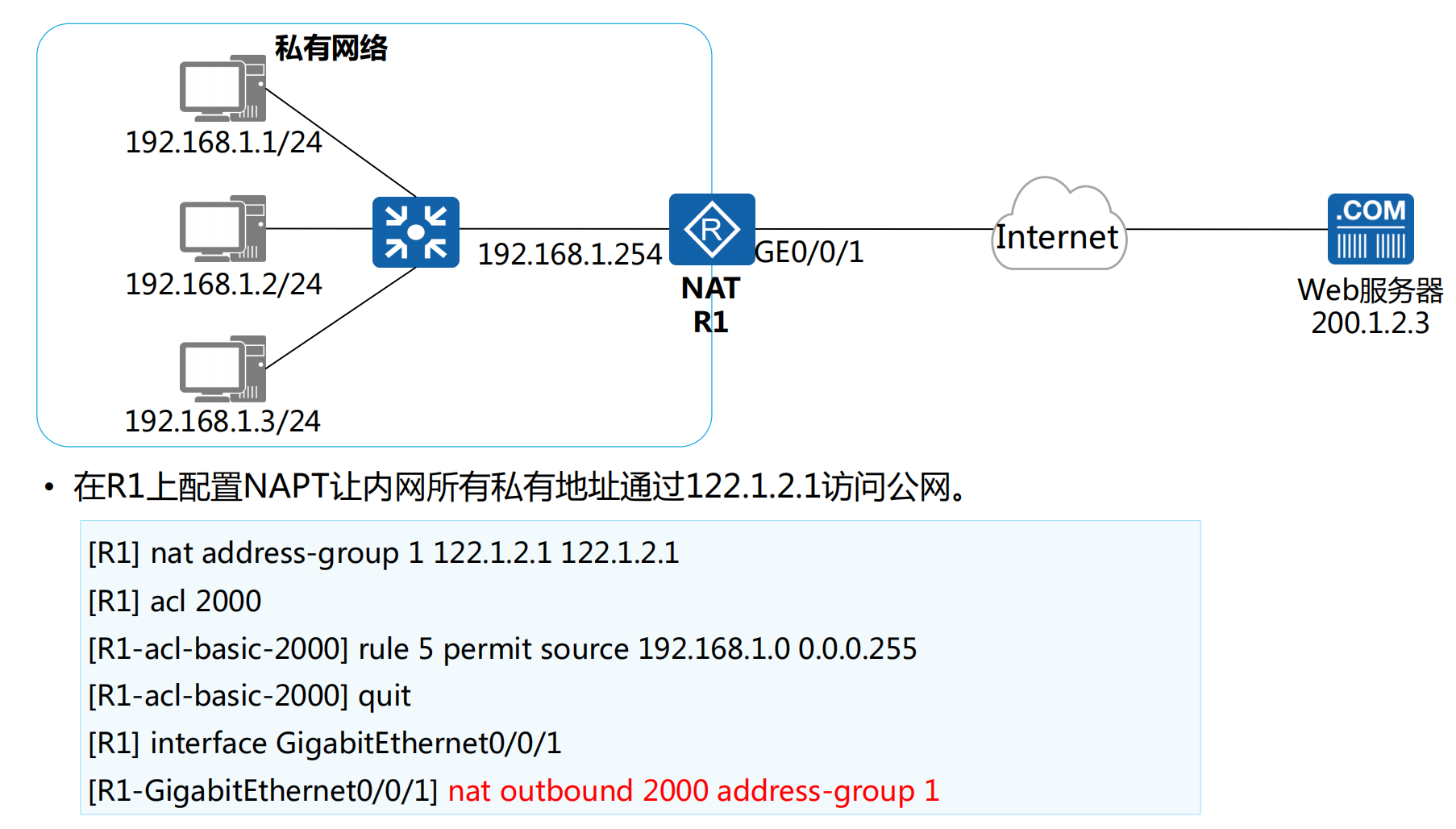
NAPT配置示例
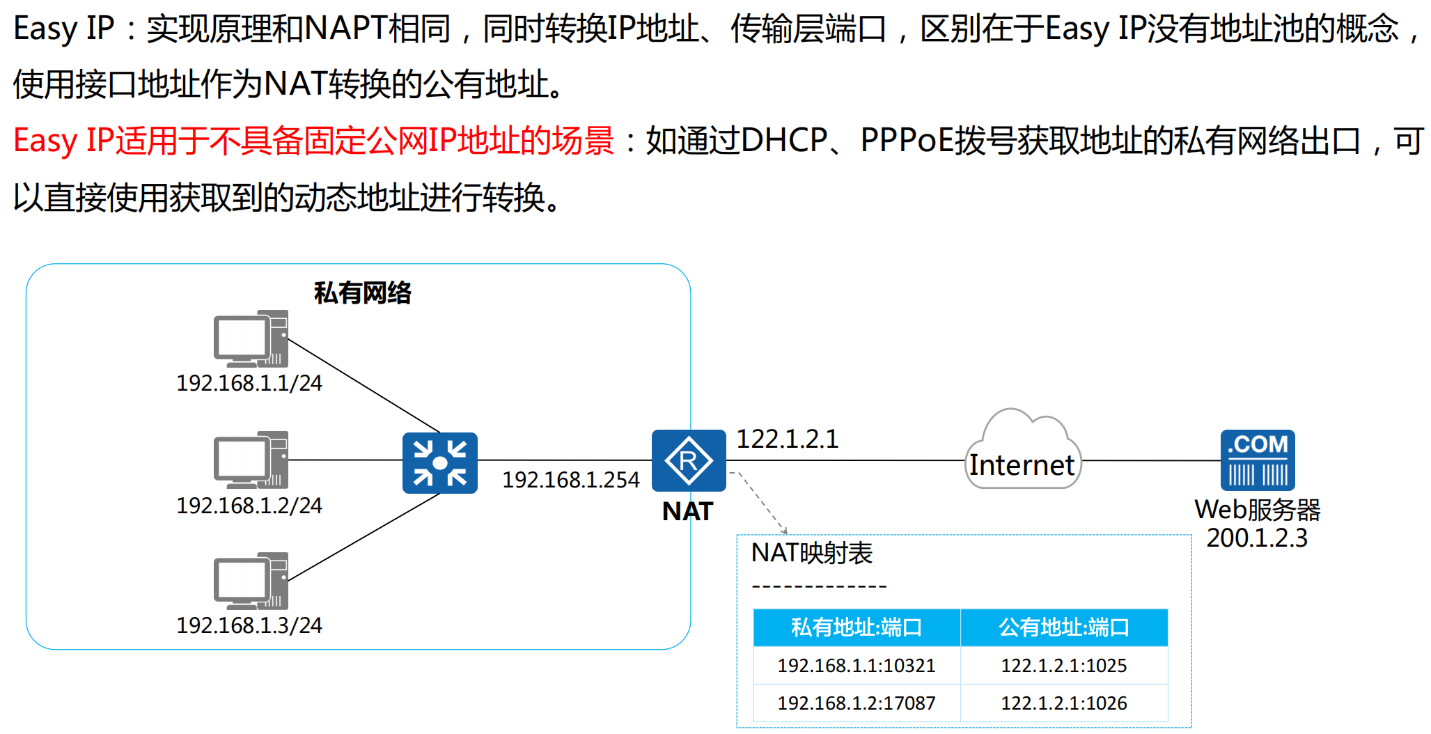
Easy IP
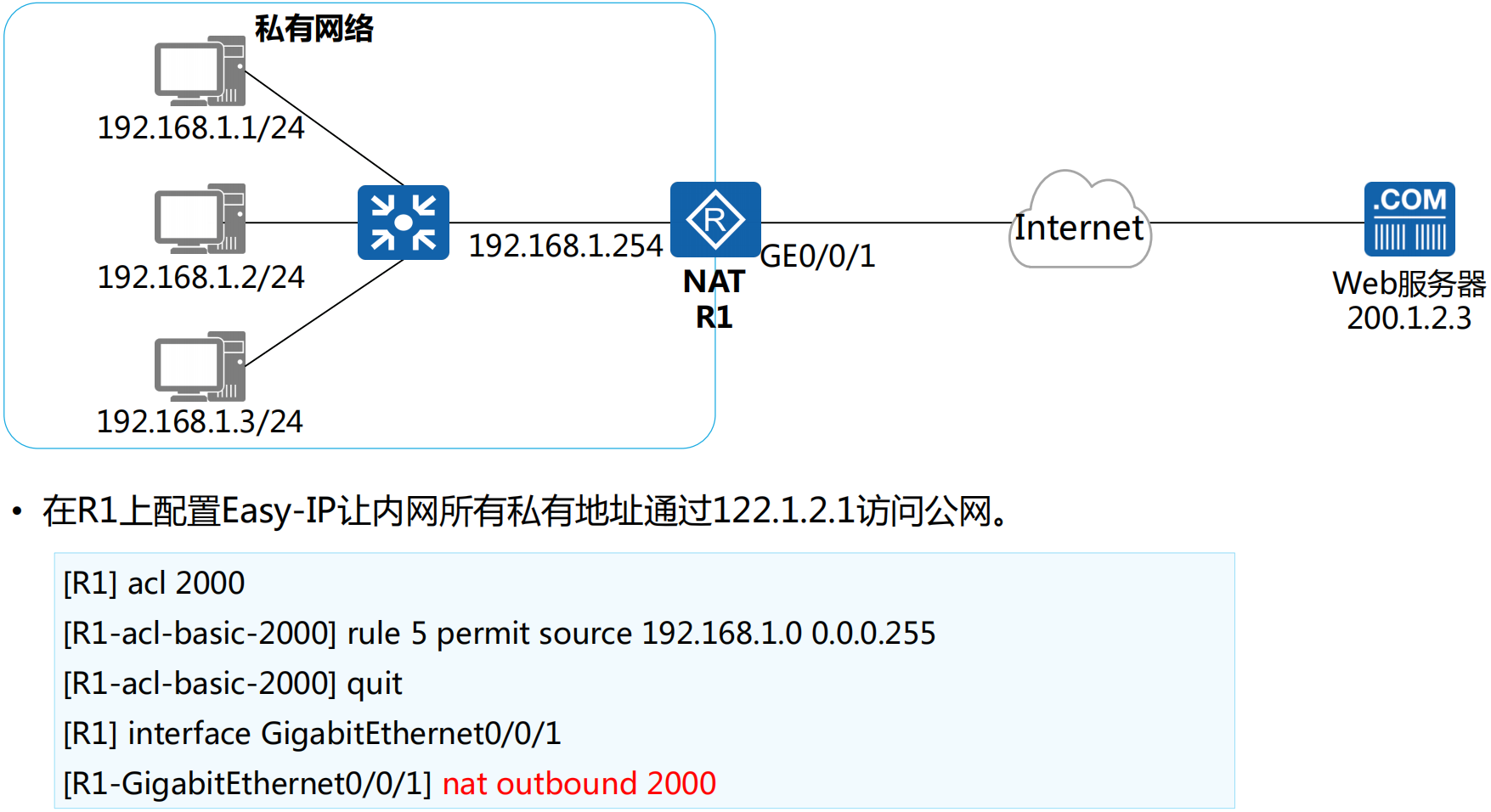
Easy IP配置示例
NAT Server
NAT Server使用场景
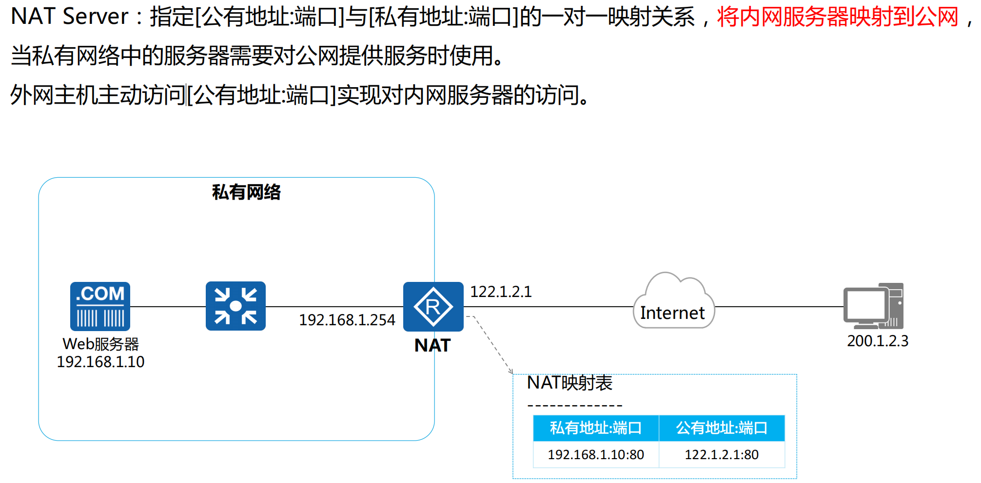
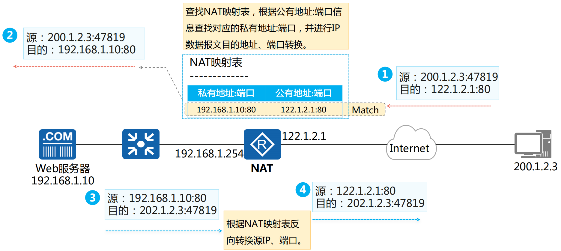
NAT Server转换示例
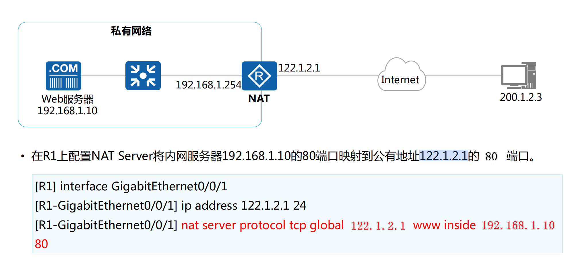
NAT Server配置示例
何种NAT转换可以让外部网络主动访问内网服务器?
1.静态NAT通过固定映射内网IP到公网IP实现外网访问,适合长期对外服务的服务器;
2.端口映射(NAPT)则通过指定公网IP和端口号将流量转发到内网服务器,节省公网IP资源且灵活性高。
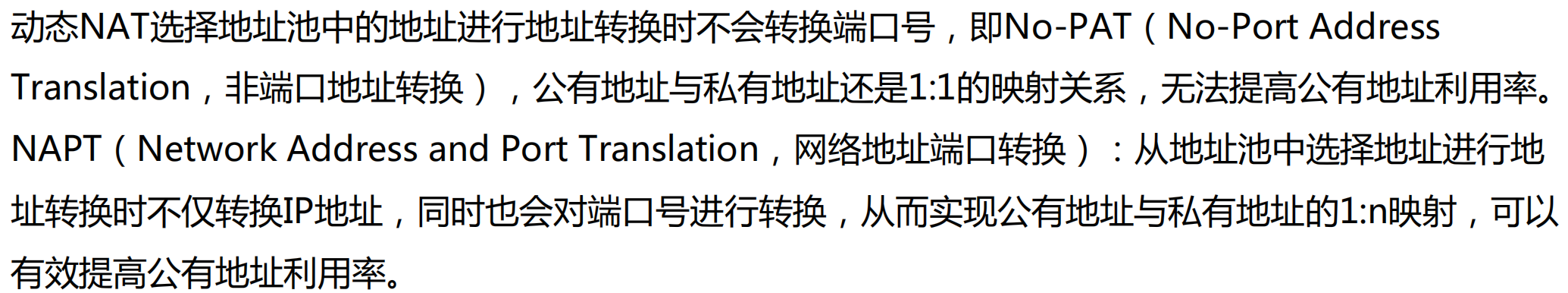
NAPT相比较于No-PAT有哪些优点?
1.NAPT相比No-PAT的优点在于能够通过端口复用技术让多个内网设备共享一个公网IP地址,从而大幅节省公网IP资源,同时支持更多内网设备访问外网。而No-PAT仅进行IP地址转换,每个内网设备需占用一个独立的公网IP,资源利用率低。
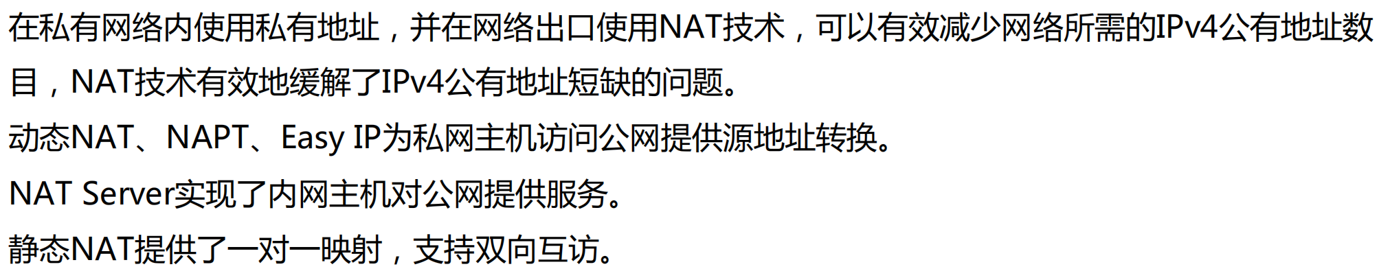
章节总结
NAT案例
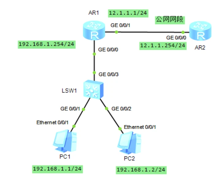
基本配置
AR1
1 | system-view |
AR2
1 | system-view |
静态NAT
功能就是内网地址和公网地址一一对应
有两个方法
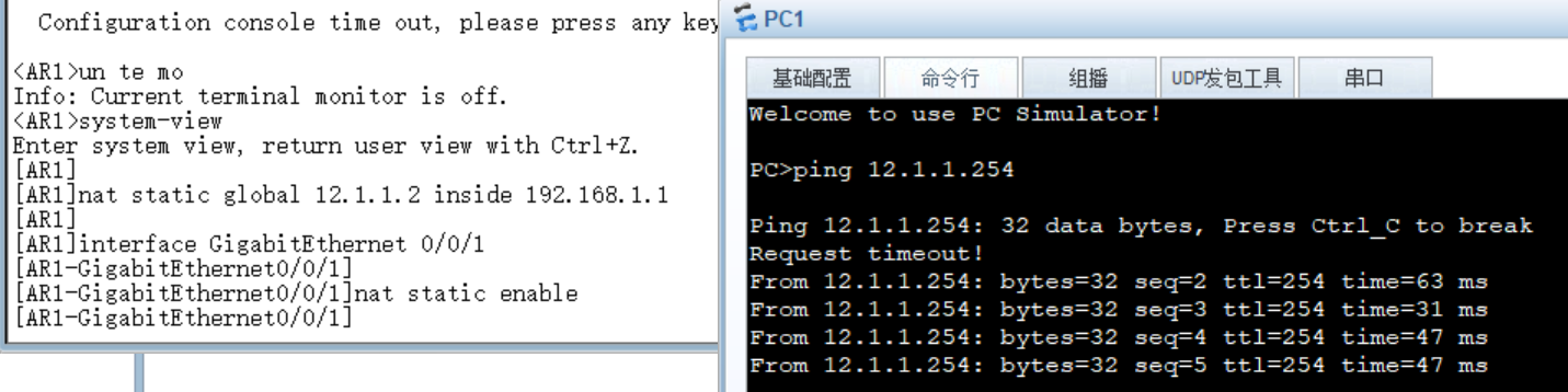
1.在接口下配
AR1
1 | system-view |
2.不在接口下配,也就是系统视图下,也就是说你虽然创建了静态nat规则,但是你没有在接口应用
1 | system-view |
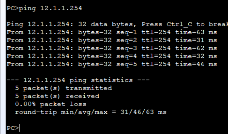
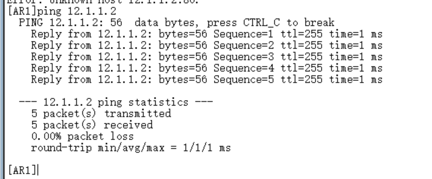
二者的区别就是,你要是在接口试图下配置nat是不用输入nat static enable
12.1.1.2是公网地址,这里的12.1.1.0/24是公网网段,也就是说 global我定义这个网段的哪一个地址都行,生产中没有这么多地址,这里就以12.1.1.2到12.1.1.10为公网地址
动态nat
有公网地址池概念,也是内网地址和公网一一对应,但是公网地址会有空闲的
删掉静态NAT的配置
AR1
在接口下配
1 | system-view |
不在接口下配
1 | system-view |
快开始配置NAT
AR1
1.创建地址池,编号为1,范围是12.1.1.2到12.1.1.10
2.创建地址转换acl
3.在接口下应用acl,并且设置为no-pat(非端口地址转换)
1 | system-view |
NAPT
接口地址转换,带端口的,这种情况只适合公网地址不多的情况,一般小公司只有一个公网地址的情况,要给公司所有内网电脑去使用,咋办呢,这时候就有了带端口的地址转换
删除动态nat的配置,前面加个undo就行了
AR1
1 | system-view |
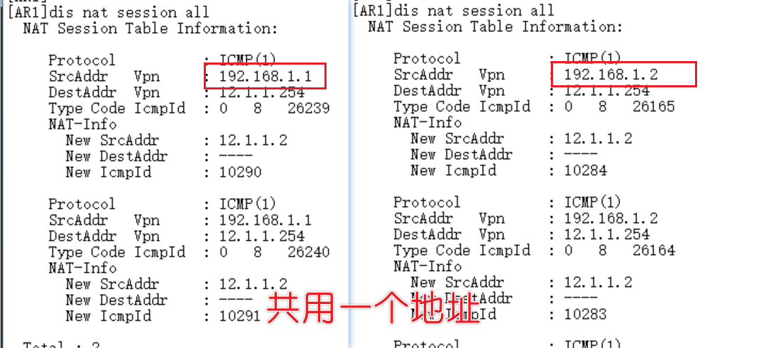
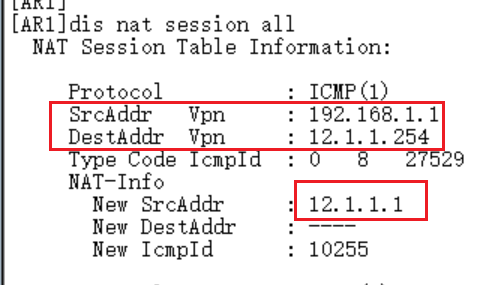
Easy-Ip
适用于没有固定的公网ip的网络,原理跟NAPT一样也是基于端口转换,把规则应用到出接口就行了,以出接口的地址为公网地址做转换
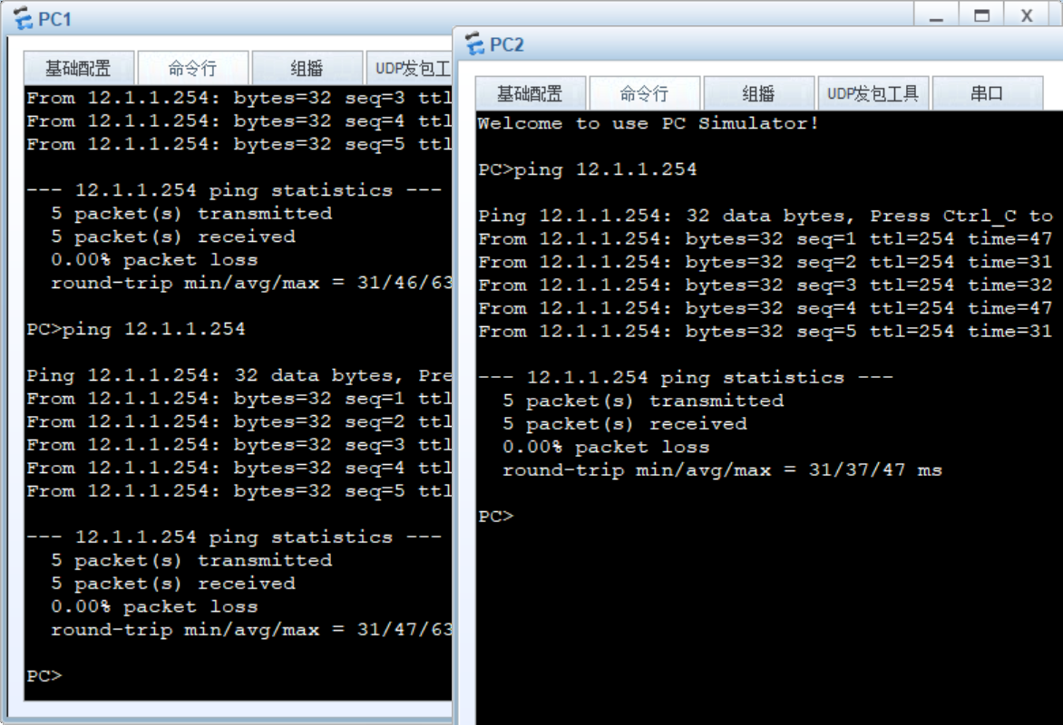
1 | system-view |
pc1一样可以ping外网
NAT Server
上面几种方法都是内访问外,我们内网主动去访问外网的,而且有了nat技术,可以保护内网地址,这样外网就不知道我们的内网地址,只知道一个公网的nat地址,那么接下来就有一种是外访问内的
一般叫它端口映射,比如说pc2是一台服务器,你部署了一个网页,那我们就把内网80端口映射到外网的80端口,这样用户就可以通过公网:80访问到我们的服务器
1 | system-view |
VRRP
VRRP概述与原理
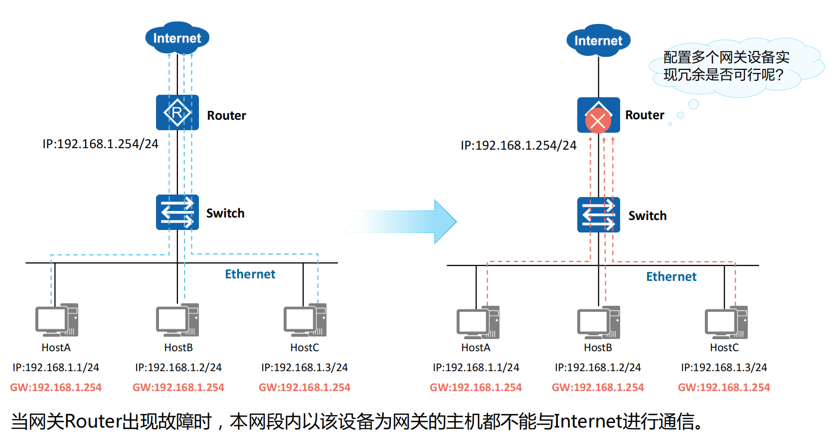
VRRP技术背景:单网关面临的问题
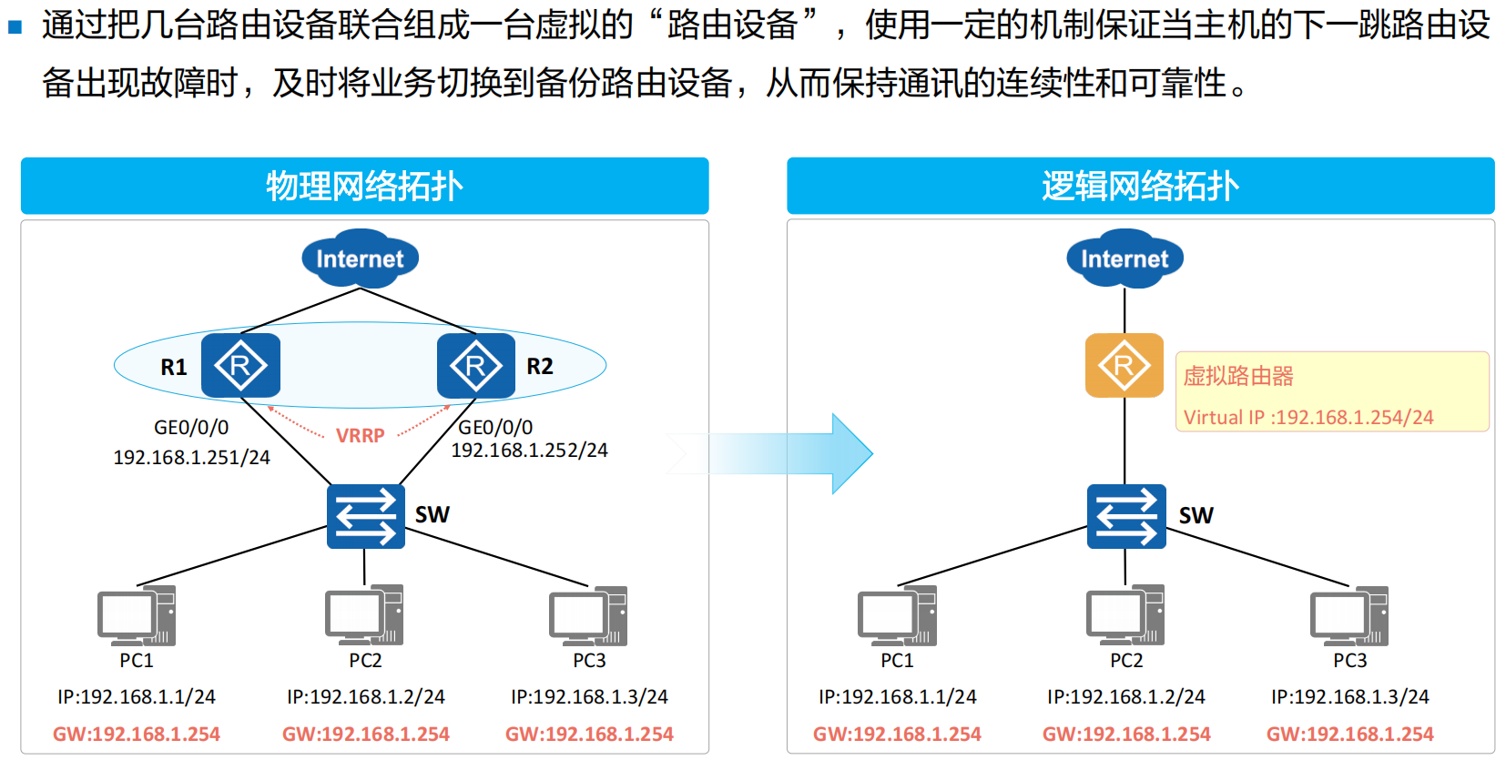
VRRP概述
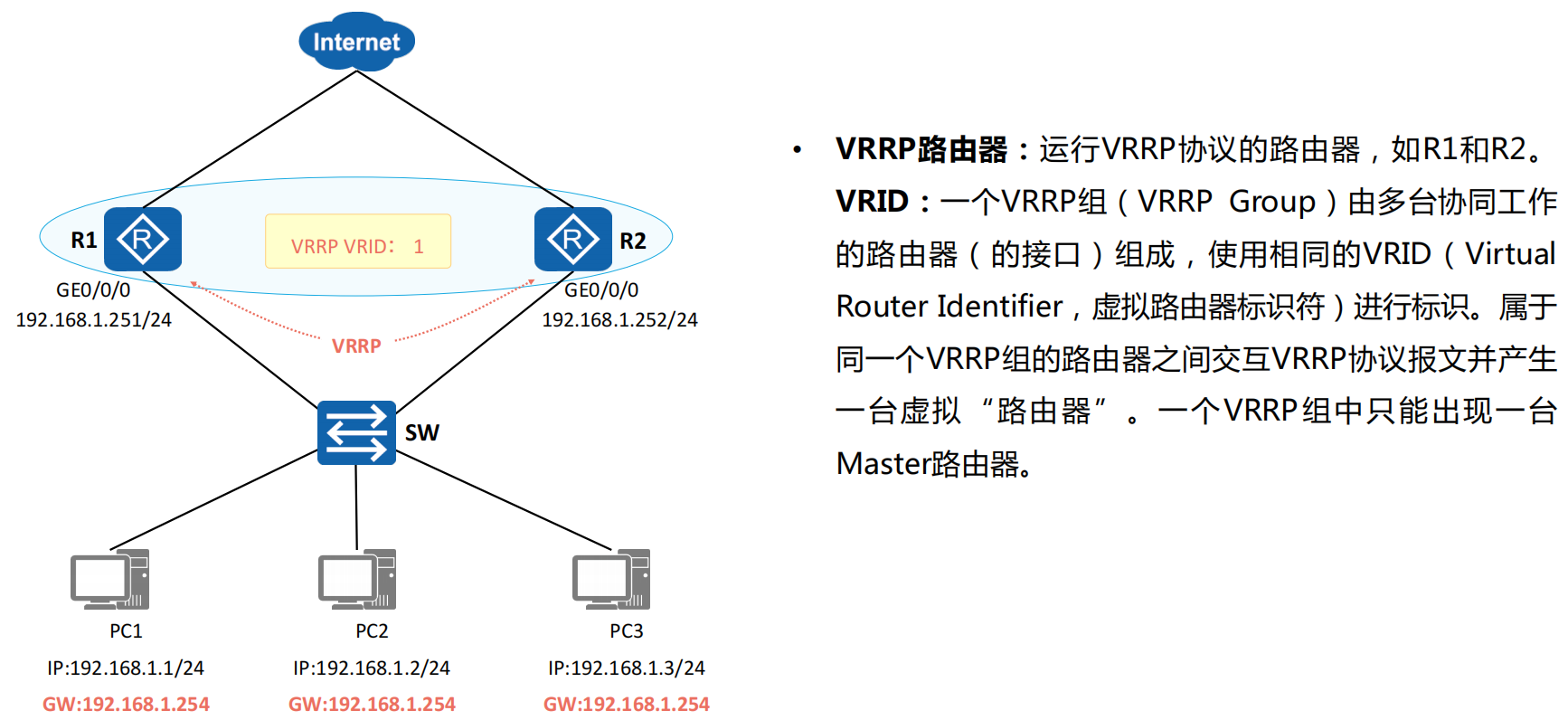
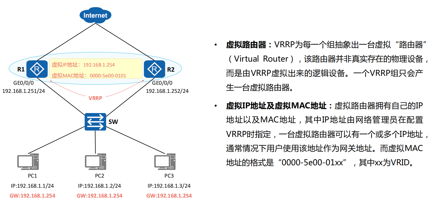
VRRP的基本概念
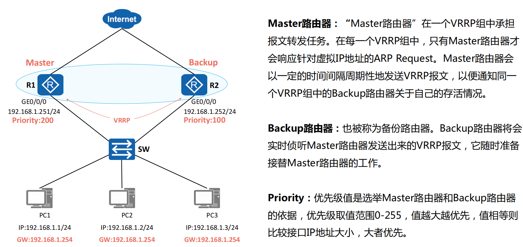
VRRP典型应用
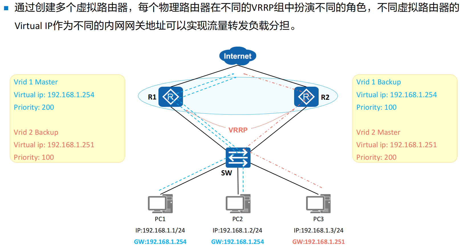
VRRP负载分担
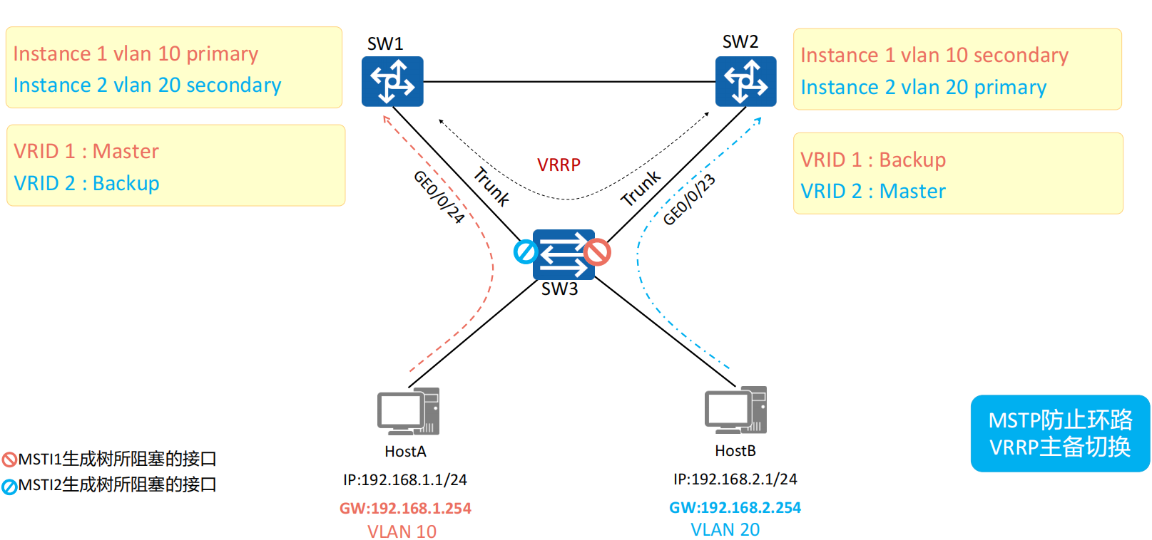
VRRP与MSTP结合应用
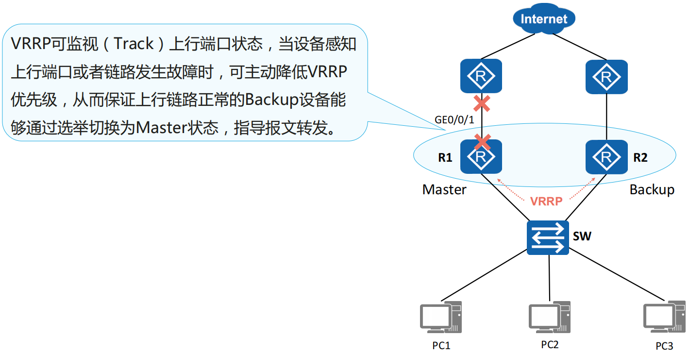
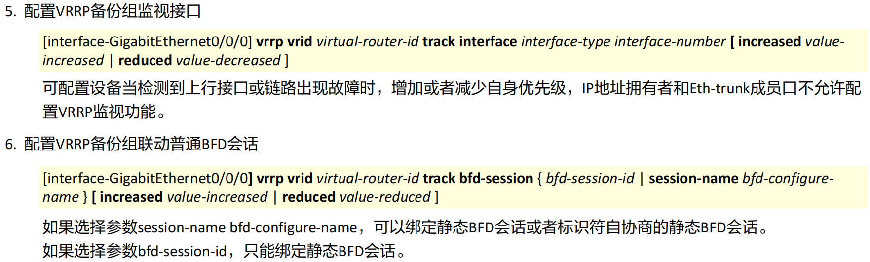
VRRP监视上行端口
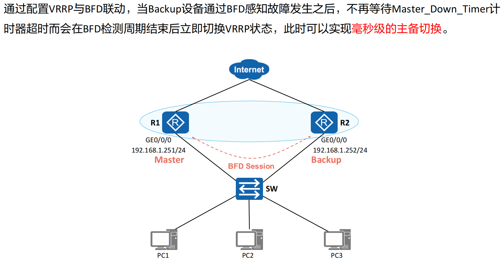
VRRP与BFD联动
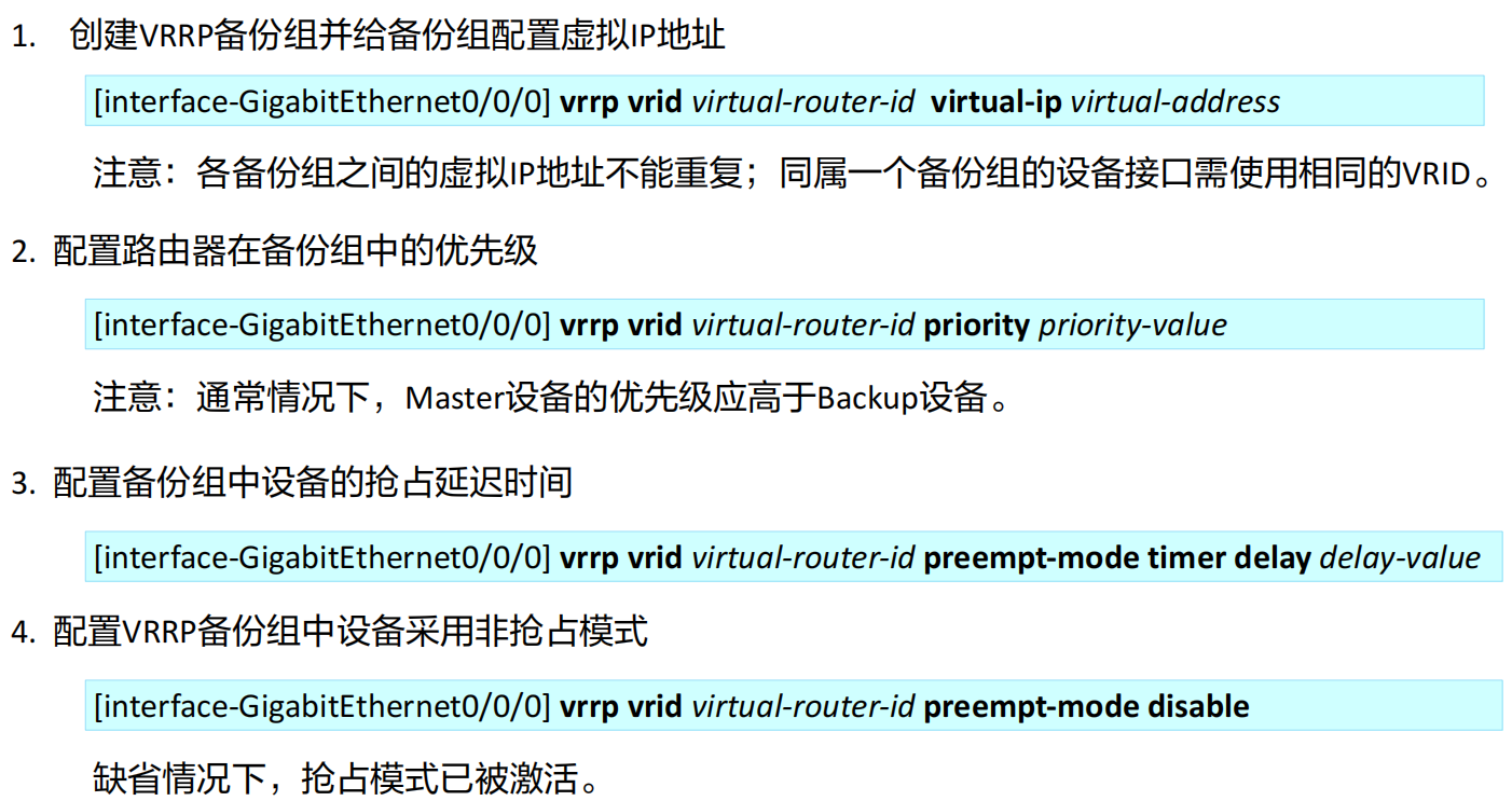
VRRP基本配置
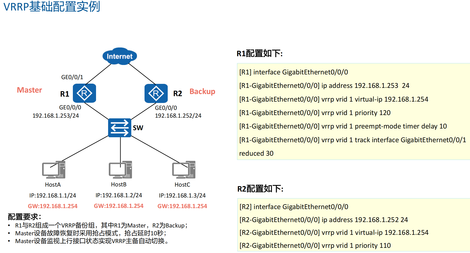
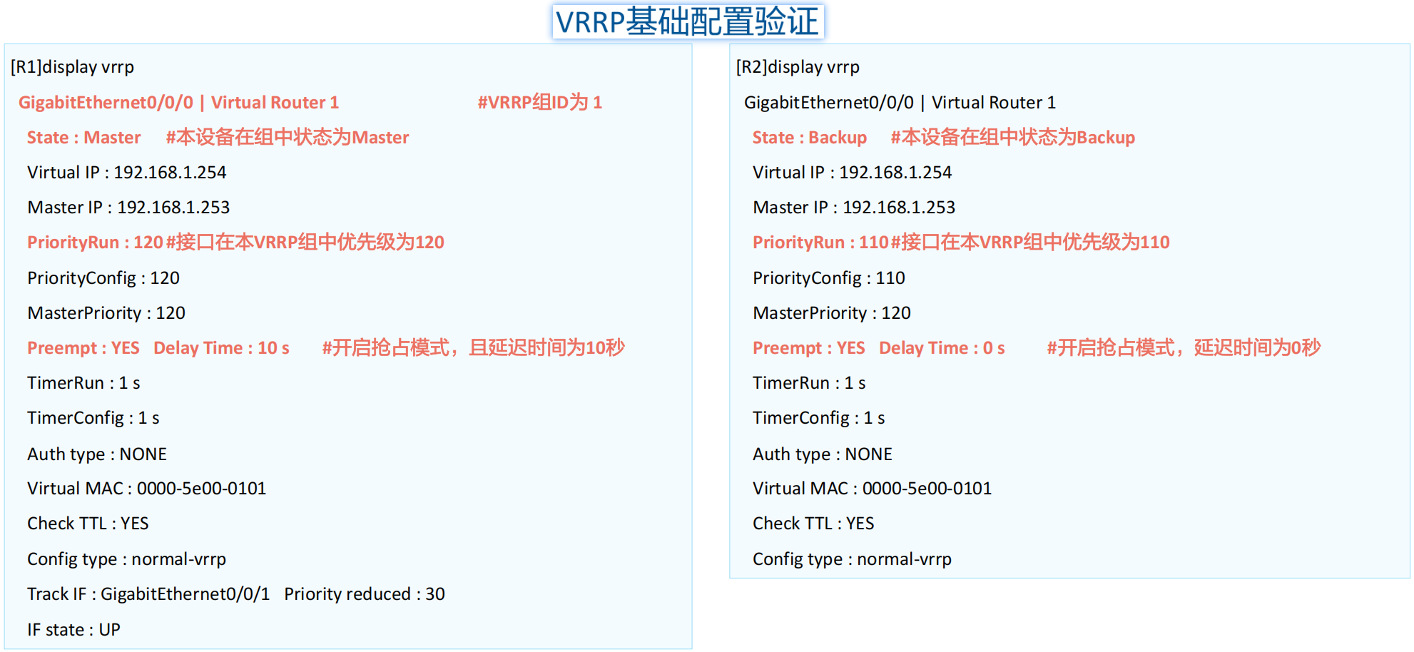
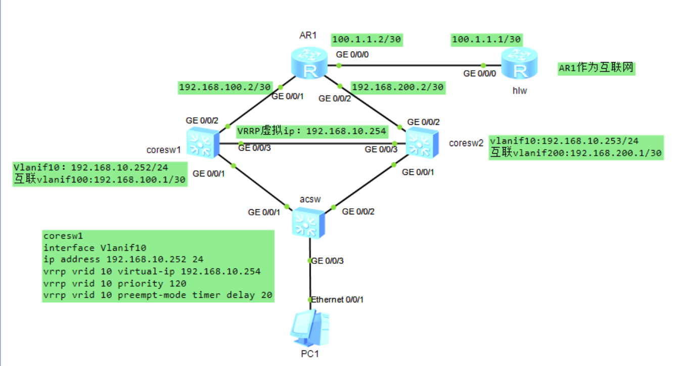
VRRP案例
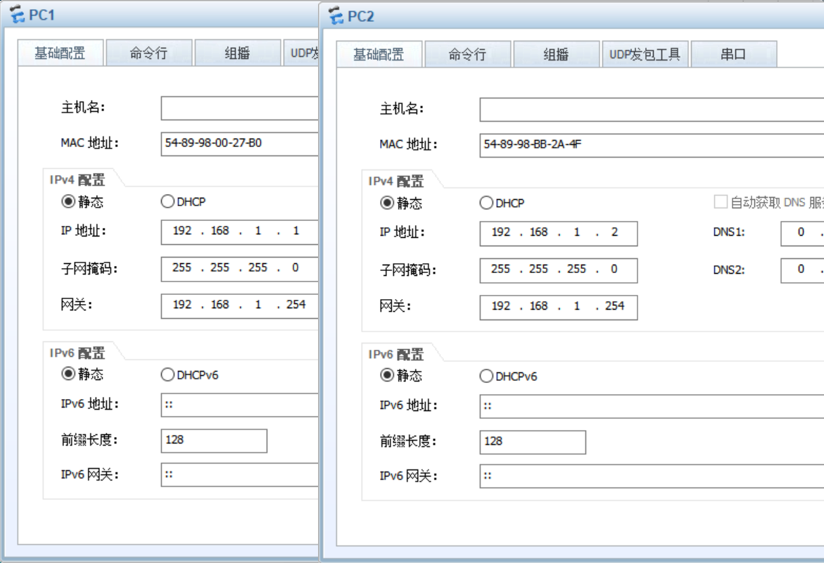
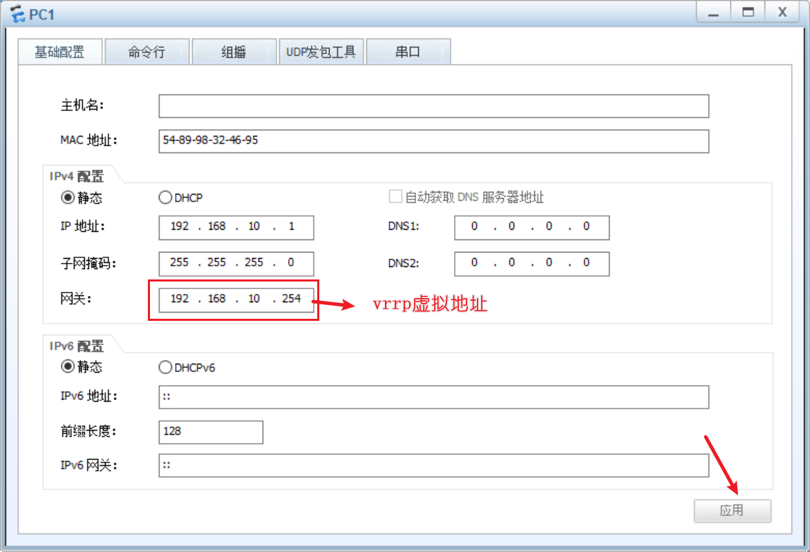
设置pc
acsw
1 | system-view |
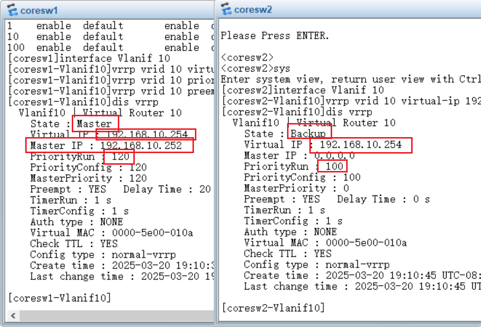
coresw1
1 | system-view |
coresw2
1 | system-view |
配置VRRP
coresw1
1 | interface Vlanif 10 |
coresw2
这里就配置优先级了,默认100
1 | interface Vlanif 10 |
AR1配置ip地址
1 | system-view |
互联网配置ip地址
1 | system-view |
测试pc1是否能与互联网互通
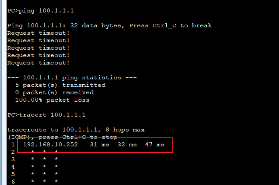
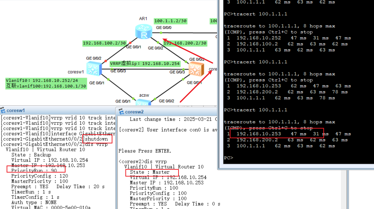
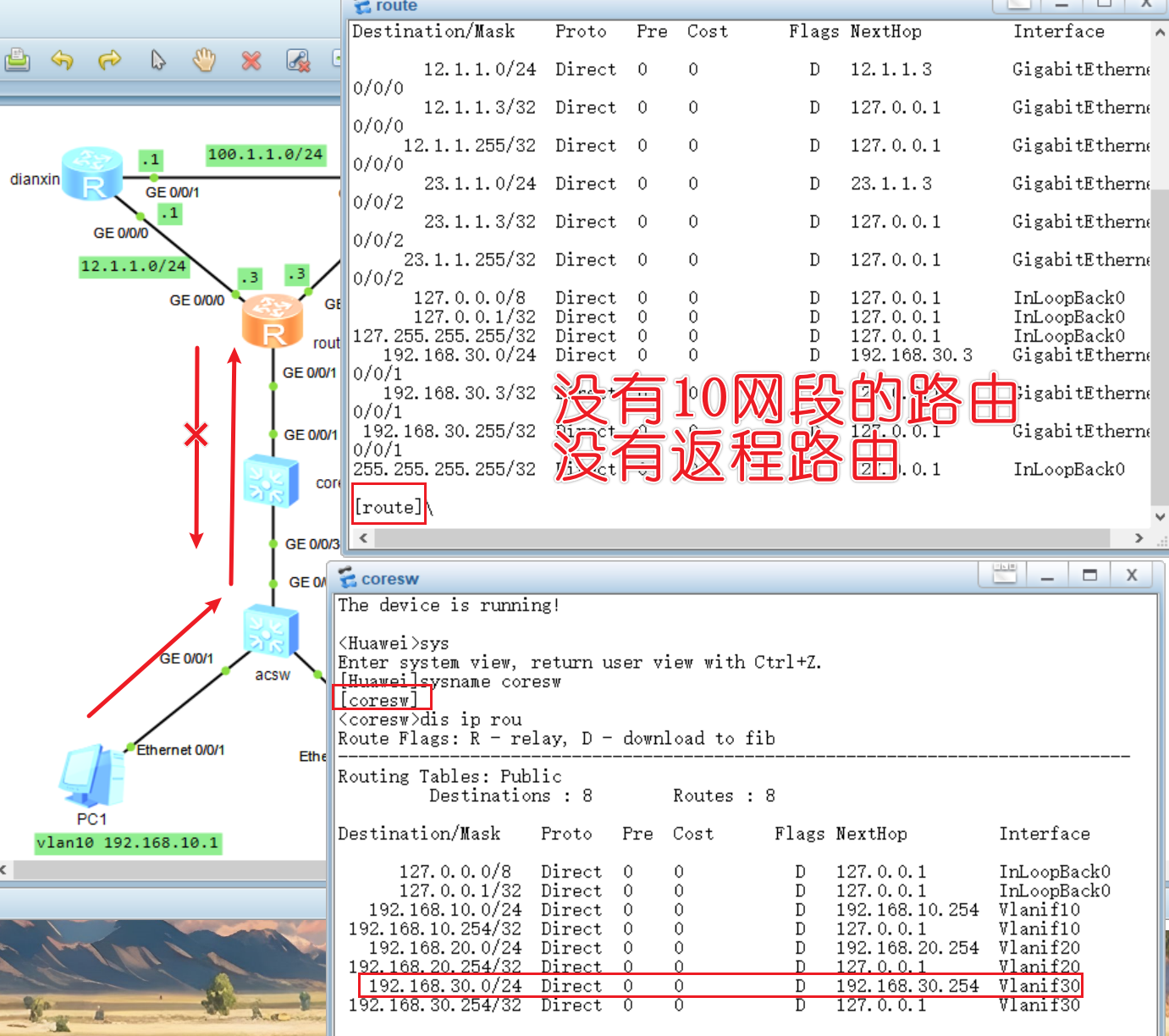
发现不能互通,经tracert检测,路由只到了coresw1,这时候查看coresw1的路由表
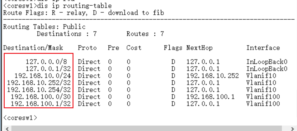
发现并没有指向100.1.1.0/30网段的路由,也就是说他只停留在了coresw1,这时候可以配一个默认路由,将所有流量指向AR1的入接口,两个核心交换机都要指向出口路由器AR1
coresw1
1 | ip route-static 0.0.0.0 0 192.168.100.2 |
coresw2
1 | ip route-static 0.0.0.0 0 192.168.200.2 |
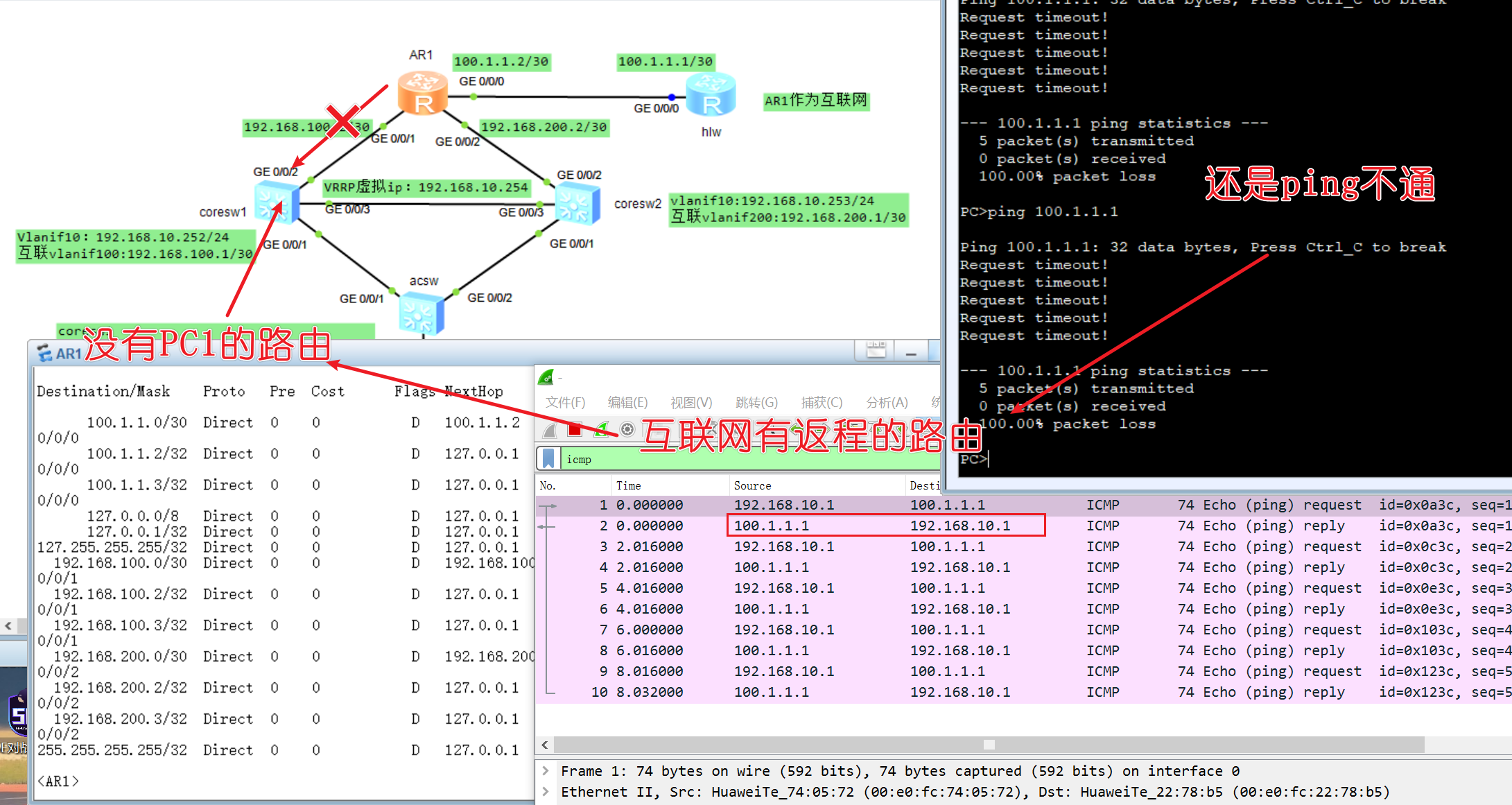
测试pc1是否能与互联网互通
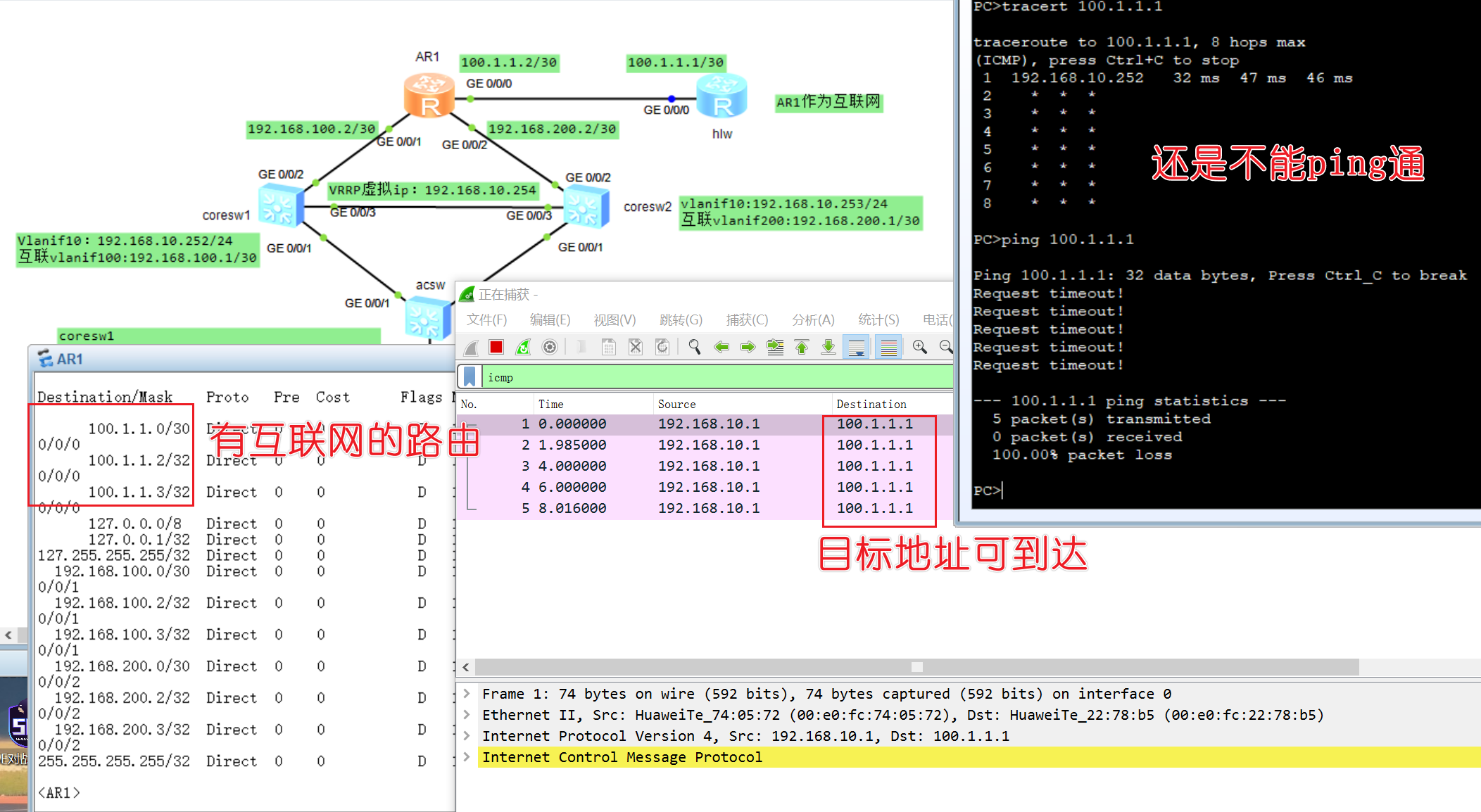
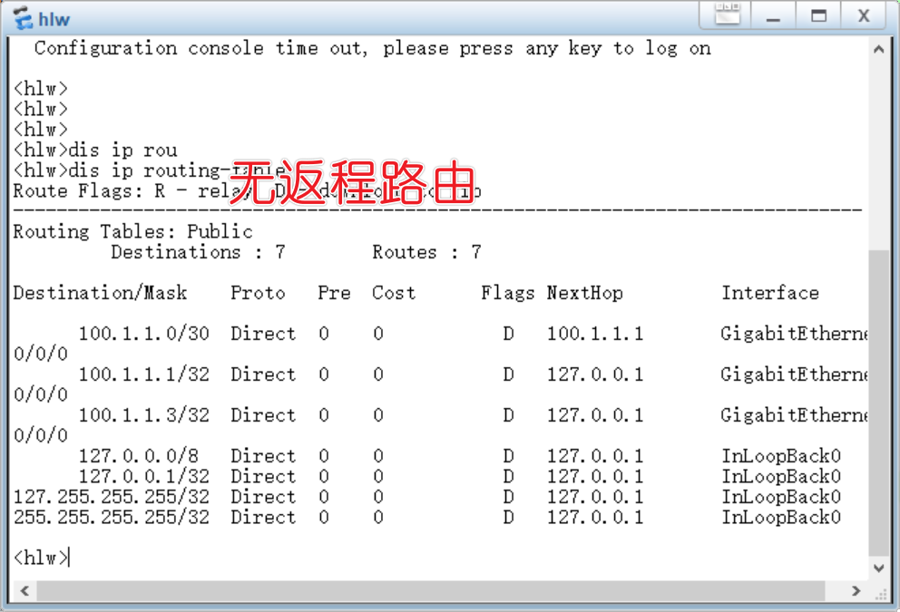
结论:抓包信息可以看到,路由可以到达互联网,但是互联网没有返程路由也就是pc1的路由,那就要给互联网配置返程路由指向AR1的如接口
hlw
1 | ip route-static 192.168.10.0 24 100.1.1.2 |
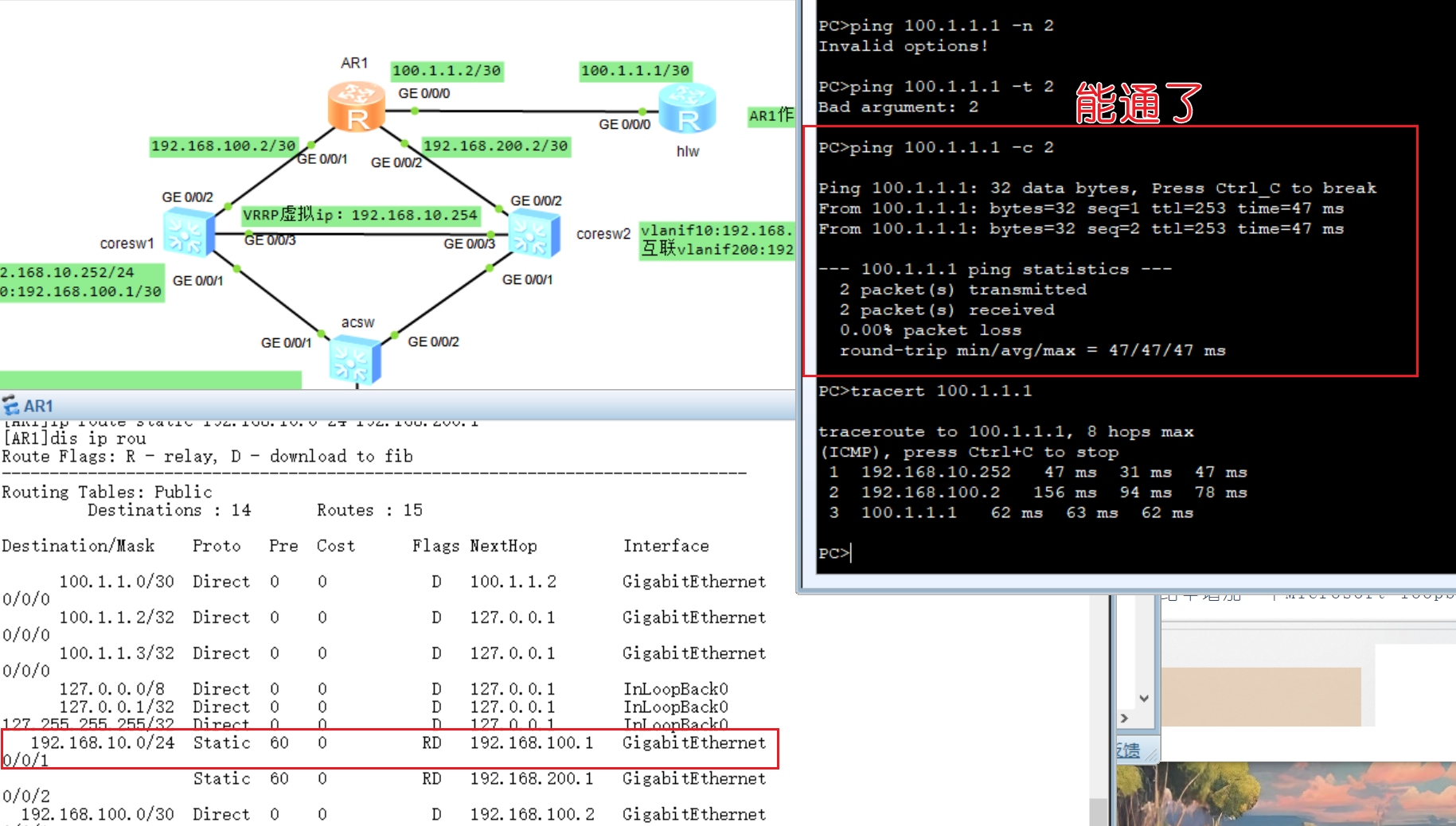
测试pc1是否能与互联网互通
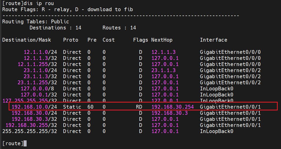
结论:返程路由192.168.10.0到了AR1,查询自己的路由表没有这个表项就丢弃了,所以要在AR1配置静态路由指向coresw1,而且也要指向coresw2
AR1
1 | ip route-static 192.168.10.0 24 192.168.100.1 |
测试pc1是否能与互联网互通
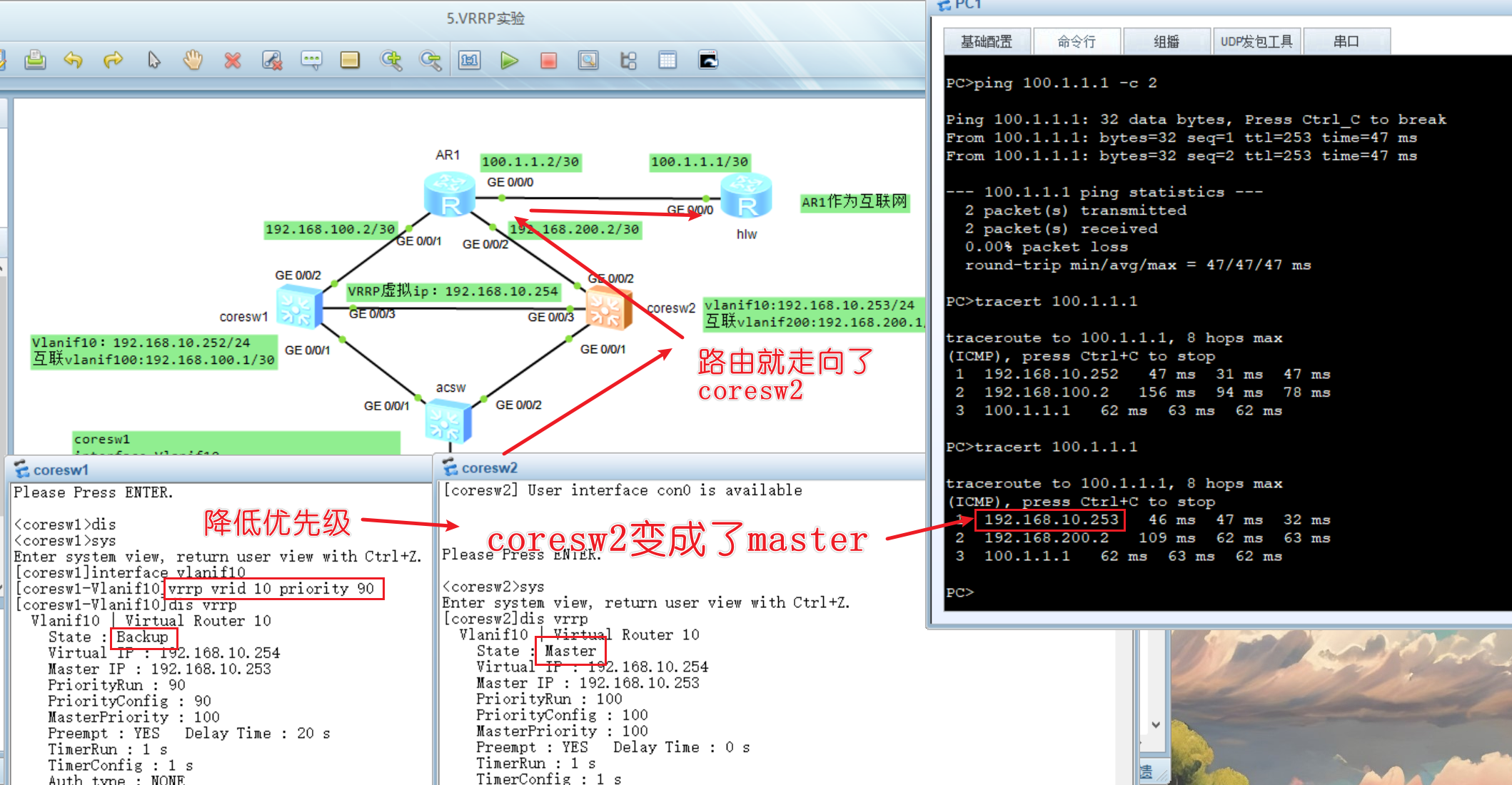
测试给coresw1设置到90优先级
1 | interface vlanif10 |
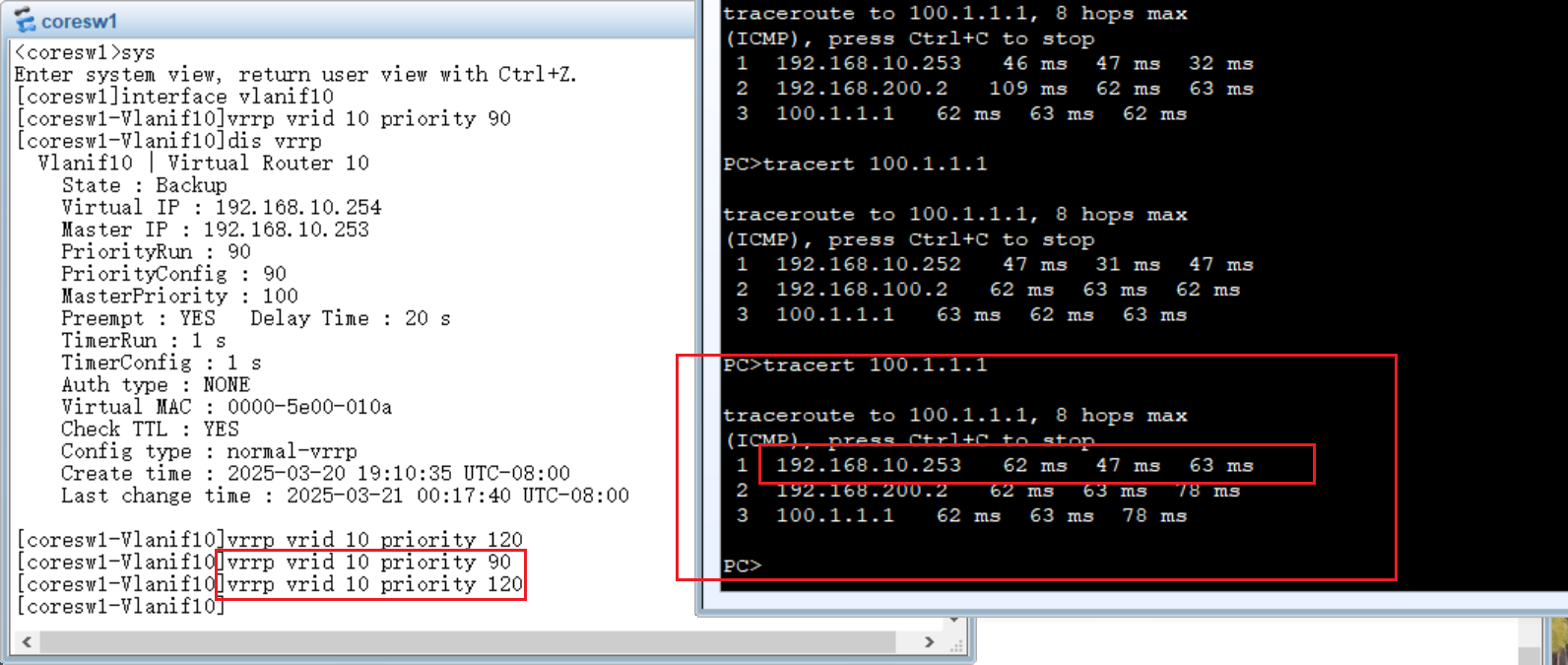
测试延迟抢占
当优先级变回120时,coresw1并没有那么快进行抢占,因为前面配置了一个20秒的延迟,等延迟过后,就会变回master
1 | vrrp vrid 10 preempt-mode timer delay 20 |
测试监视上行接口
coresw1
监视g0/0/2,如果g0/0/2 down掉了,那么coresw1的优先级就会减30变成90,则coresw2的优先级默认就是100就会大于coresw1,变成master
1 | interface vlanif10 |
浮动路由与BFD监视
目的:在出口路由器配置默认路由指向联通和电信,主要实现,当电信挂了,默认路由就会指向电信路由器,以此达到浮动路由的目的
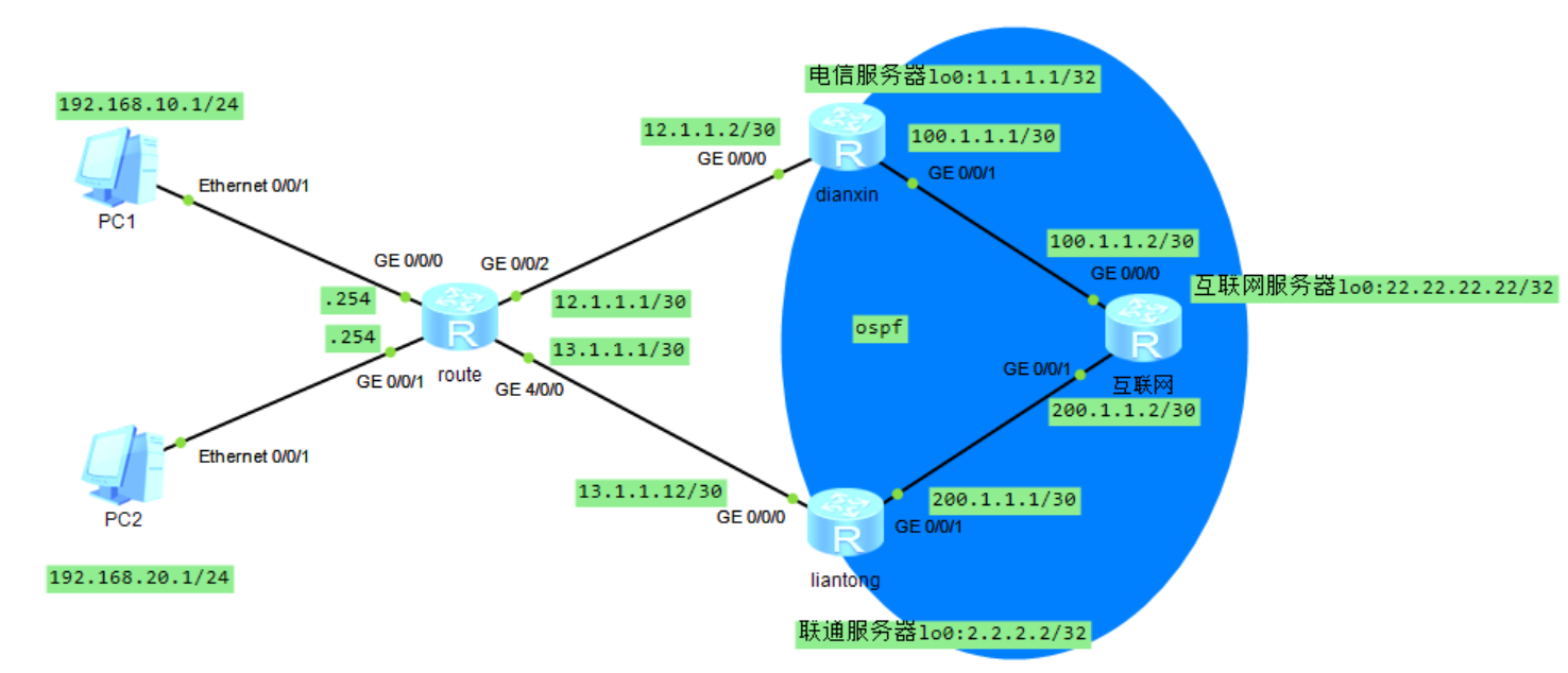
配置IP地址
route2000
1 | system-view |
dianxin2001
1 | system-view |
liantong2002
1 | system-view |
互联网2003
1 | system-view |
配置OSPF
dianxing,互联网,liantong
这样做的目的,会把自己直连的路由宣告出去
1 | ospf 1 |
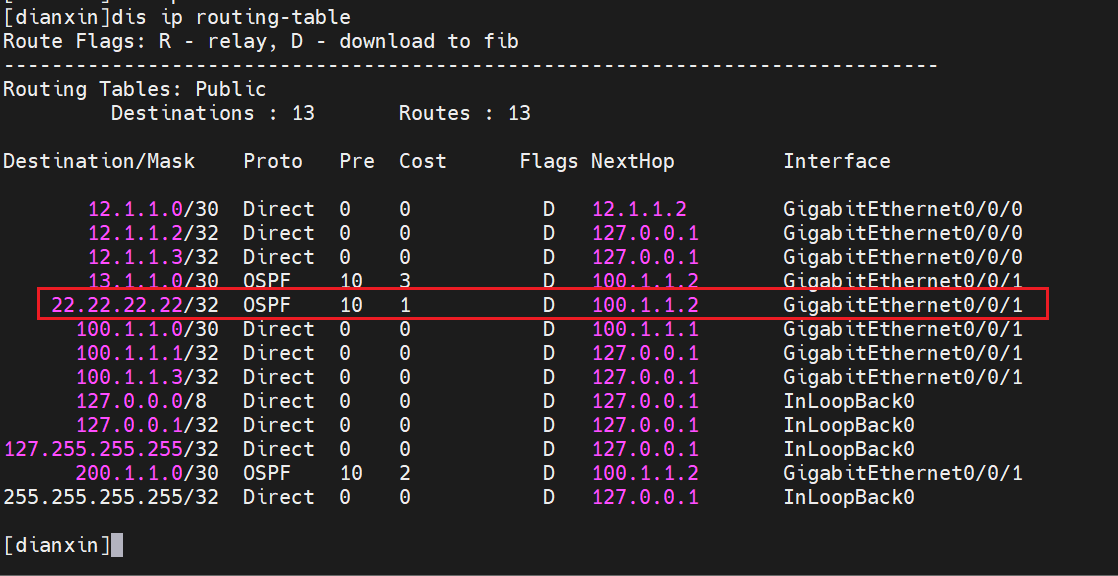
电信路由器,已经学到了ospf区域内设备的直连路由,其他设备也一样
配置nat
接着,在route(角色:出口路由器)配置nat,假设他不具备固定的公网ip地址,把内网路由转换到出接口
route
1 | acl 2000 |
还要配两条静态路由指向运营商,考点:出口路由器都要配置默认路由
1 | ip route-static 0.0.0.0 0 12.1.1.2 |
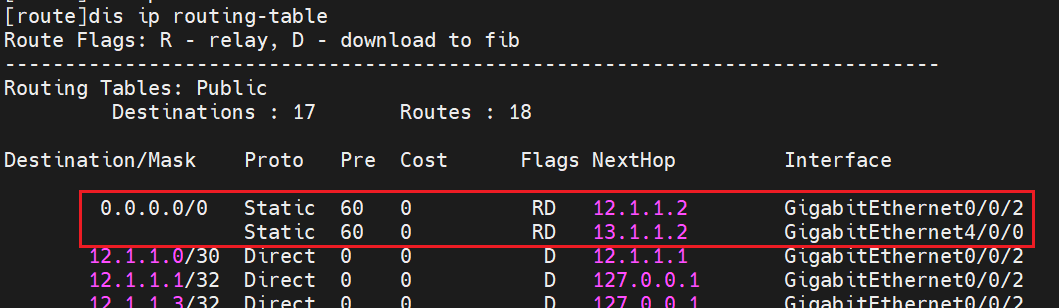
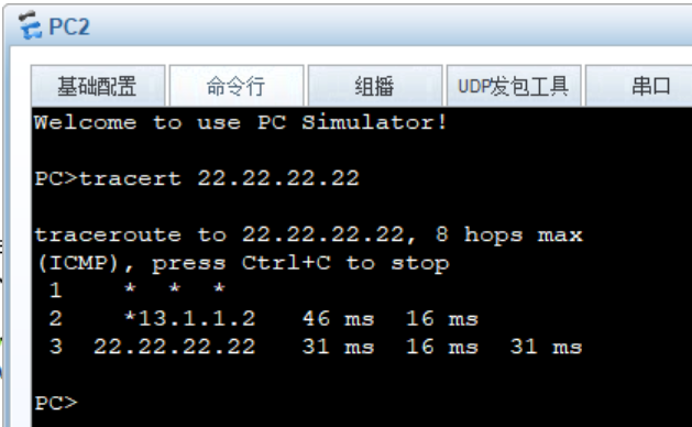
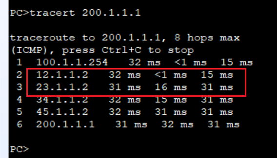
由于我使用的路由器是AR2000系列的,中低端路由器,他是不支持基于包来做流量的负载均衡,所以,当进行tracert 22.22.22.22你会发现,他的每一次路径都是走联通的,了解一下就行了
配置浮动路由
原先配置了两条等价路由,现在为了达到,开头的目的,就必须先把走向联通的路由器的优先级调高,这样越小越优先,就会走向电信路由器
route
1 | ip route-static 0.0.0.0 0 13.1.1.2 preference 100 |
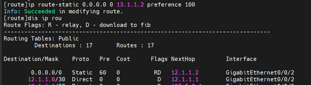
这时候你会发现,只有一条指向电信的路由了,这就是浮动路由,调成100的优先级就不优先了,就会被隐藏起来,当你电信的默认路由,掉了,指向联通的路由才会显现出来,接下来就模拟这个浮动路由的实验
1 | int g0/0/2 |
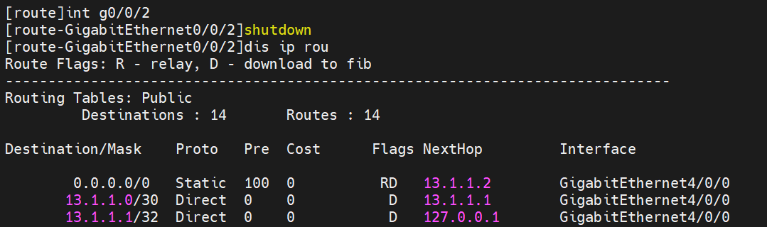
这时候指向联通路由就会出来,保证了业务的连续性
1 | int g0/0/2 |
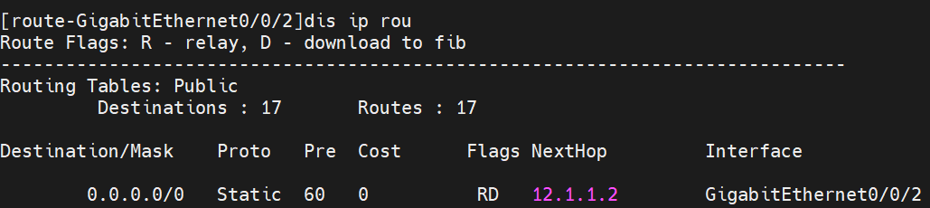
等几秒就会回来了
而且,不管是以下图片哪个接口down了,他都会实现浮动路由到联通
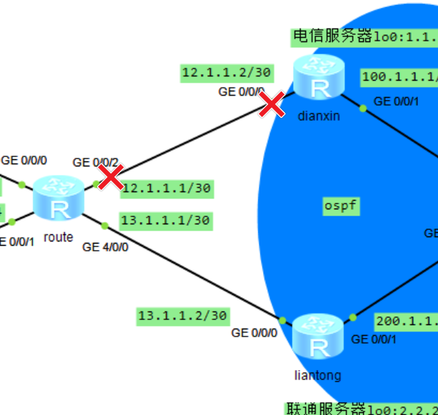
BFD监测网络状态
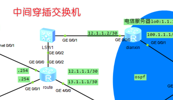
背景
背景:我们前面不是配置了指向电信的默认路由吗,但是现实情况,不可能说出口路由器直接与运营商去互联的,中间肯定经过很多层交换机,路由器啥的,现在就来模拟这个实验,就会影响我们的浮动路由
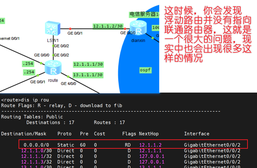
这时候将电信路由器的g0/0/0口断掉,查看情况
dianxin
1 | sys |
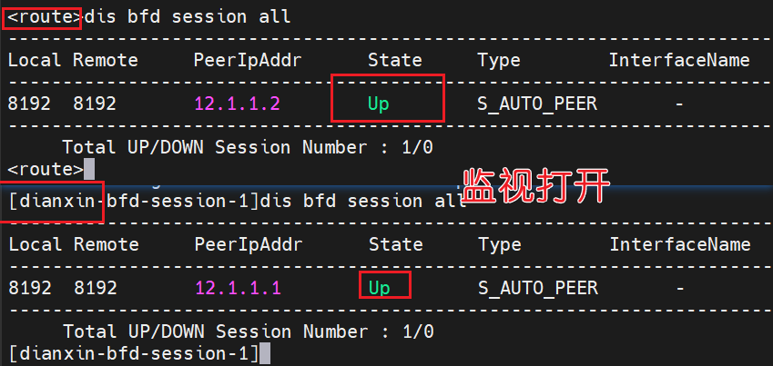
配置bfd
接下来就在dianxin和route配置bfd,来达到双向检测,如果监测断掉之后,就可以实现浮动路由
route
1 | bfd |
dianxin
配置这个之前,你要把原来的g0/0/0接口打开,不然即使创建了规则,也会报错
1 | int g0/0/0 |
接口没打开,你配置了就会报这个错,接口开启来就行了,没事

接下来在指向电信路由器的默认路由配置bfd监视,当这个bfd 1的监视器出现了down的情况,那么这个默认路由就会被删掉,从而实现浮动路由
route
1 | ip route-static 0.0.0.0 0 12.1.1.2 track bfd-session 1 |
当dianxin的g0/0/0接口断掉之后
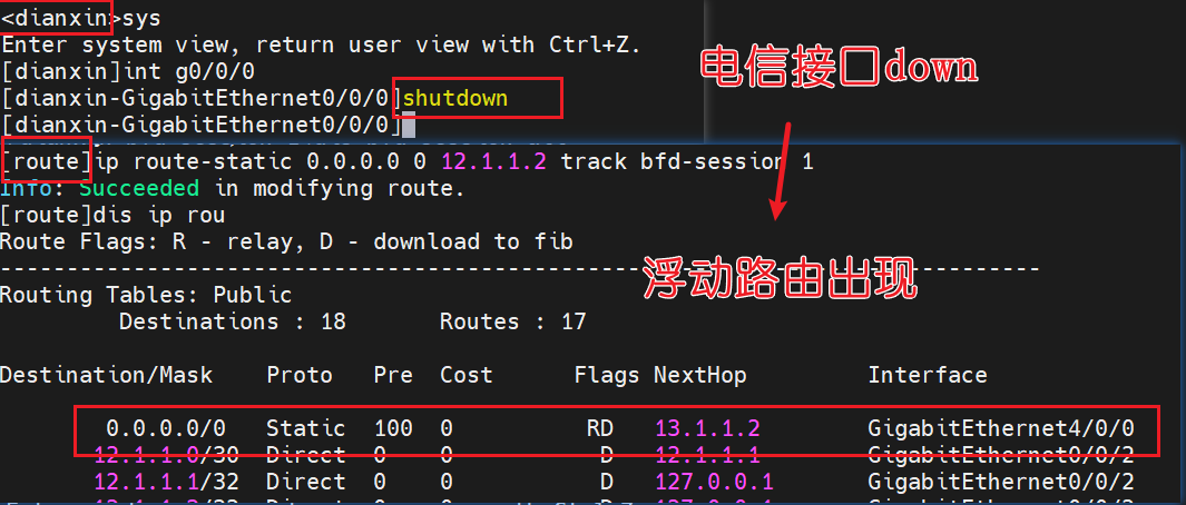
走的是联通服务器
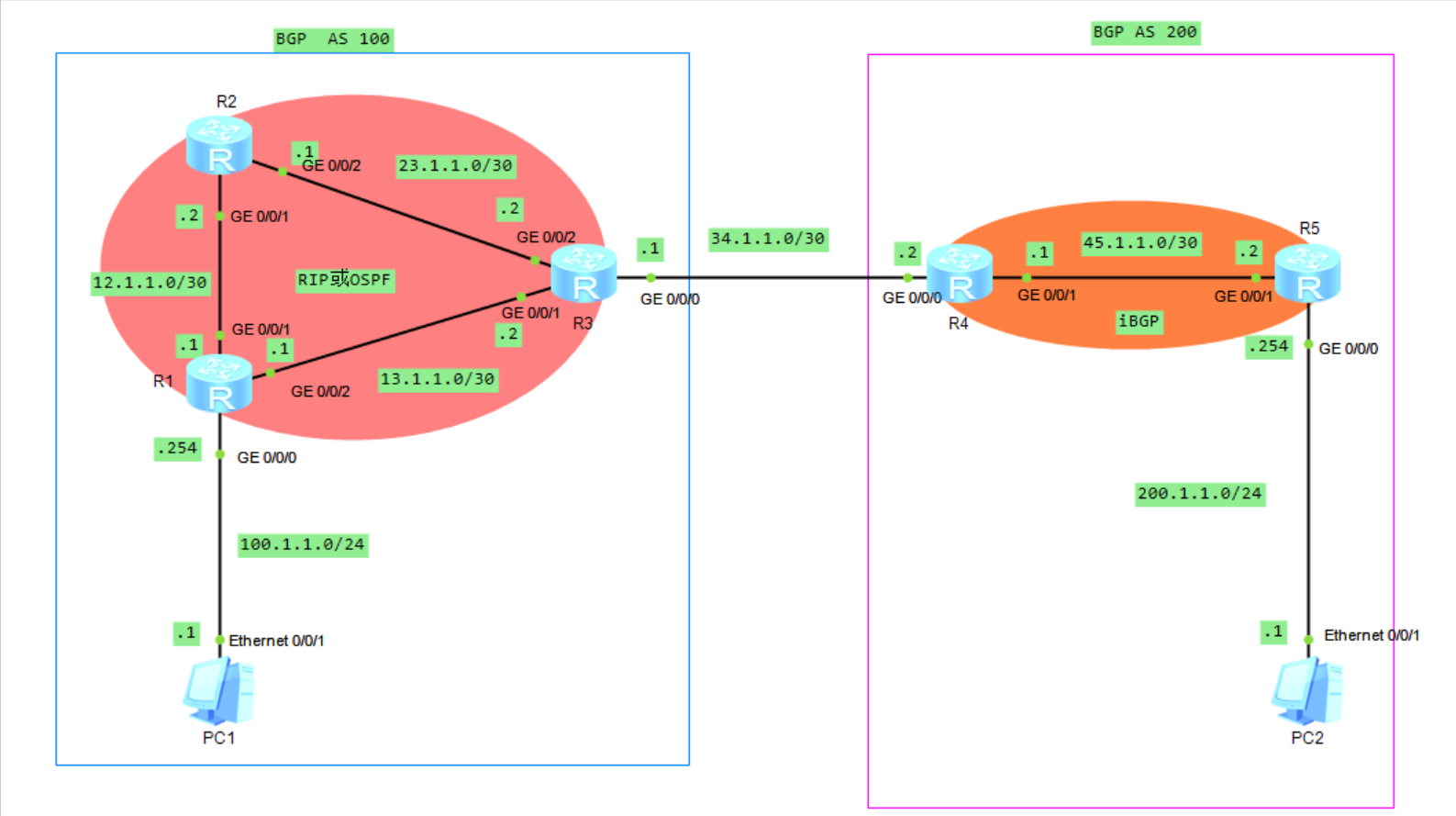
路由综合实验RIP OSPF BGP
目的:中间通过ospf或rip,然后经过bgp之间学习路由,达到PC可以互通
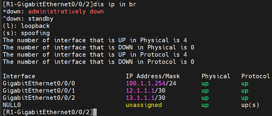
配置IP地址
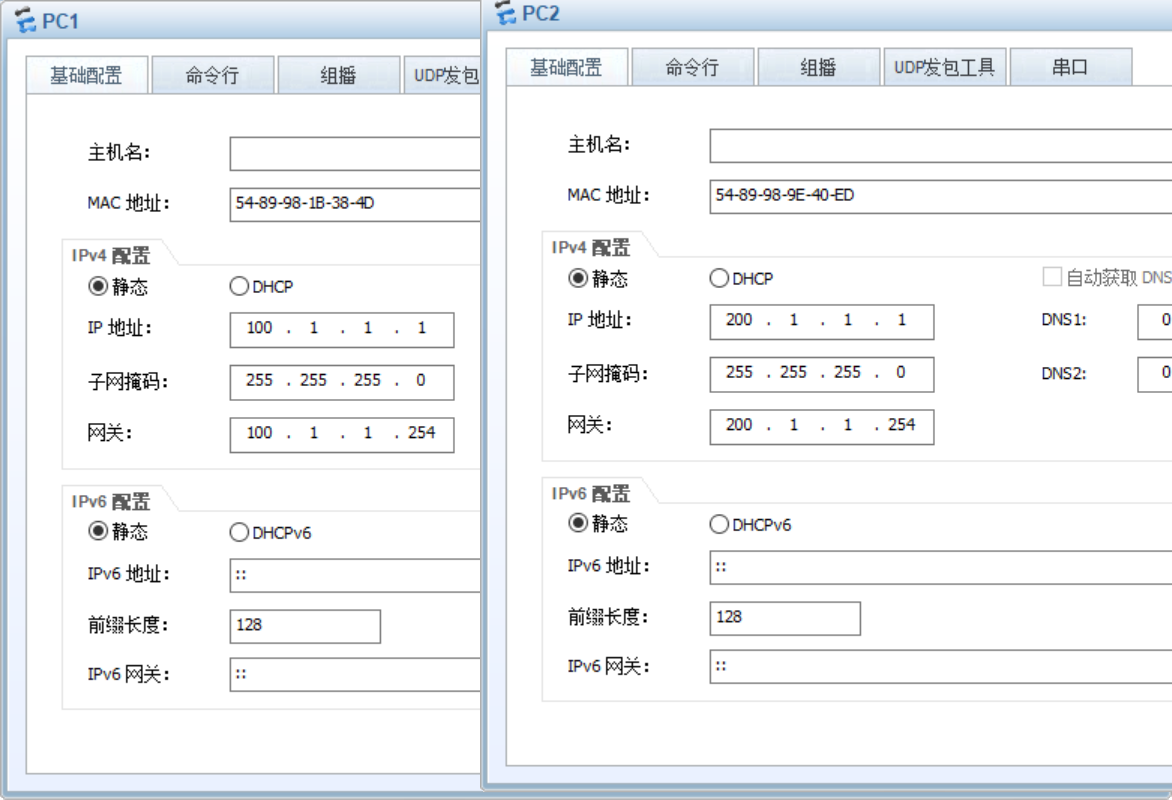
PC1、PC2
R1
1 | system-view |
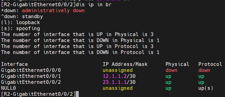
R2
1 | sys |
R3
1 | sys |
R4
1 | sys |
R5
1 | sys |
配置RIP(与osfp二选一)
配置rip宣告网段时,例如R2宣告12.1.1.0的网段时,会报错,一般生产中都会配置ripv2,由于他的路由自动汇总,他会把12.1.1.0汇总到更大的网络12.0.0.0,因为这些地址都是A类地址,所以rip就默认自动汇总到12.0.0.0,目的是减少路由表的大小,提高网络的可扩展性。
A类地址范围:1.0.0.0-126.0.0.0 /8
B类地址范围:128.0.0.0-191.255.0.0 /16
C类地址范围:192.0.0.0-223.255.255.0 /24
R1
1 | sys |
R2
1 | sys |
R3
1 | sys |
配置完检查一下3个路由的路由表
1 | dis ip rou |
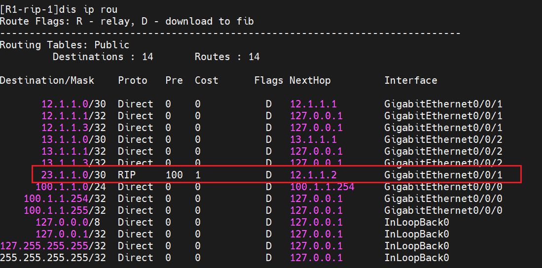
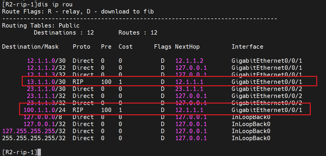
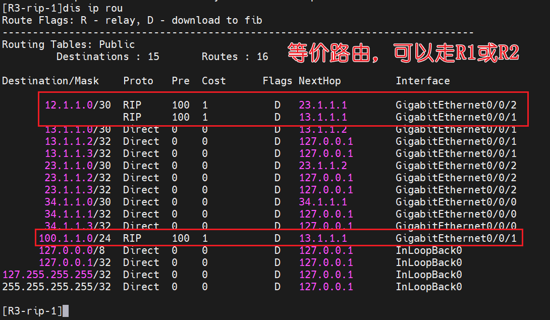
RIP区域内的路由器,通过rip学习到各个路由器宣告的路由,但是如果其中有自己直连的路由信息,就没有rip路由显示,本身就是直连的嘛,只会学习到没有的
配置OSPF(与RIP二选一)
由于我前面配置了rip,这里要演示ospf我就删掉前面的rip配置,如果你没有敲前面的rip就不用执行下面的删除rip配置的命令
R1,R2,R3
1 | sys |
接下来正式配置ospf,它宣告网段的方式和rip是不一样的,要加上反掩码,而且没有rip的自动汇总,是可以直接写网段的
R1
1 | sys |
R2
1 | sys |
R3
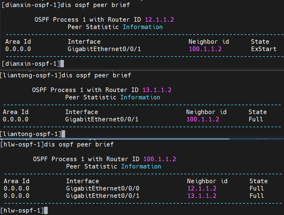
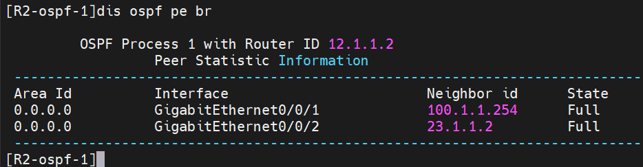
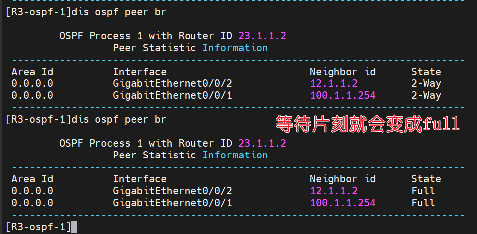
1 | sys |
1 | dis ospf peer brief |
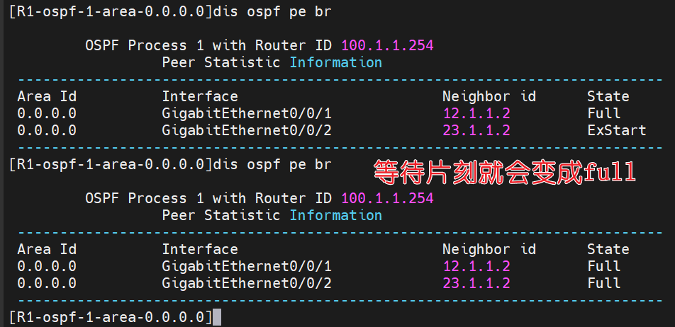
这时候查看路由表
1 | dis ip rou |
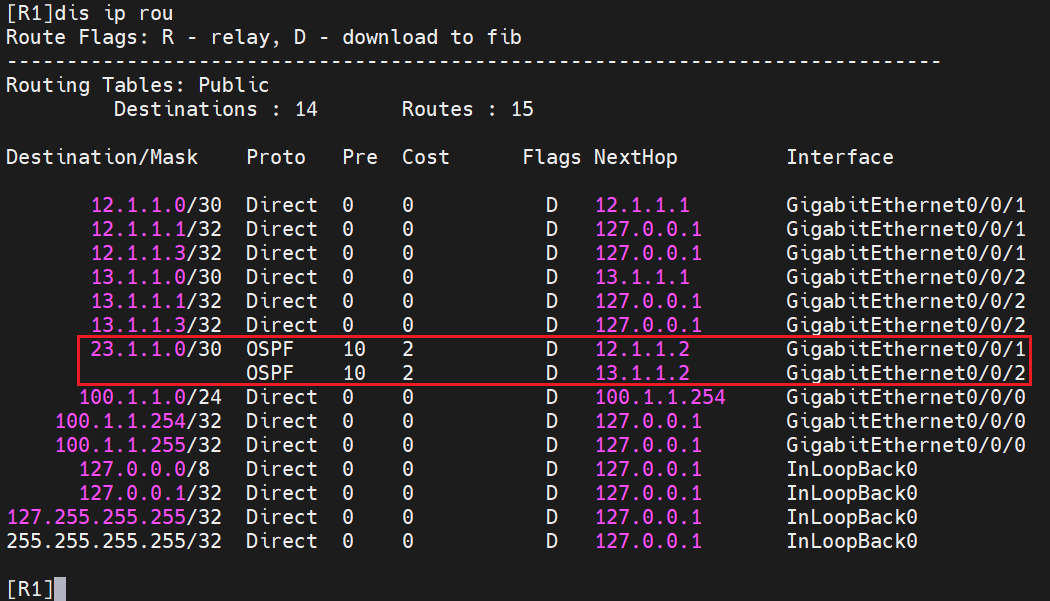
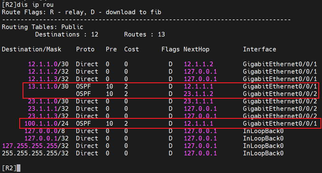
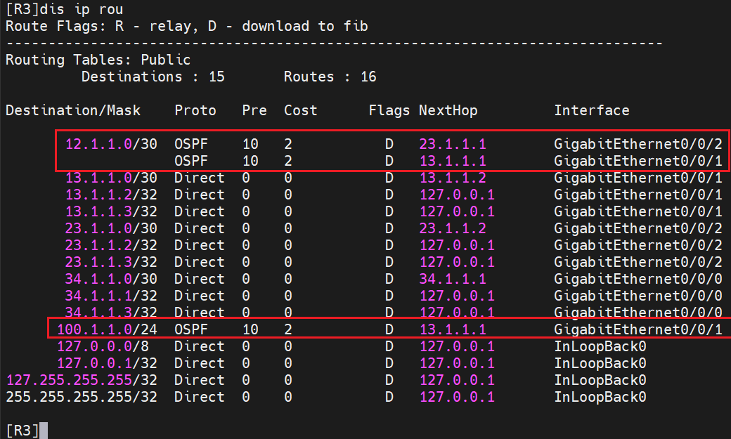
ospf也和rip一样,就可以学习到其他路由器宣告的,非直连的路由
以上是RIP和OSPF的配置过程,就是了配置IGP协议进行一个自治系统(AS)内部交换路由信息的协议
IGP可以进一步划分为两类:距离矢量路由协议和链路状态路由协议。常见的IGP协议包括RIP(路由信息协议)、OSPF(开放最短路径优先)和IS-IS(中间系统到中间系统)等。
- RIP:使用跳数作为路径选择的度量标准,适用于小型网络。
- OSPF:基于链路状态的协议,使用Dijkstra算法来计算最短路径,适用于中型到大型网络。
- IS-IS:也是一种基于链路状态的协议,类似于OSPF,通常用于ISP和大型企业网络中。
配置bgp
- BGP:边界网关协议(Border Gateway Protocol)是一种具体的外部网关协议,是EGP的一种实现。BGP是互联网中使用最广泛的外部网关协议,用于在自治系统之间进行路由信息交换。取代
EGP
R3 他在BGP AS 100 ,要填写领居也就是对端的信息,构建领居关系
1 | sys |
R4
1 | sys |
R4
1 | sys |
等待片刻,查看R4是否与R3和R5建立领居关系
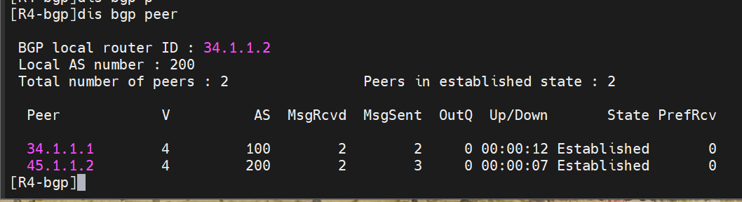
Established相当于ospf的full,图中已经成功建立了,查看R4的路由表
1 | dis ip rou |
这时候并没有bgp的路由,为啥,因为bgp的特殊性,需要手动宣告和将其他路由器学到的路由导入到本路由器才行
接下来会演示两种方法
手动宣告路由
R5将200.1.1.0的网段宣告进IBGP里,在BGP中,通过ipv4-family unicast命令进入IPv4单播地址族视图后,可以使用network命令来宣告哪些IPv4网络将被加入到BGP的路由表中,并向其他BGP对等体发布。这样其他bgp路由器就可以学习到这个网段
1 | sys |
一看,R3和R4都学到了这个路由
引进路由
首先我们可以先,pc各自的网关,是否有对方网段的路由
1 | dis ip rou |
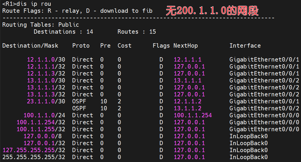
也就是说,pc1无法ping pc2的,各自的网关都没有对端的路由。
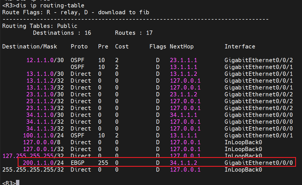
但是R3刚刚不是经过R5手动宣告路由学到了200.1.1.0的路由吗,这是R3要将右边学到的bgp路由信息引入到ospf里
1 | sys |
如果是rip,就进入到rip version2里一样的输入import-route bgp
这时候查看R1的路由表,已经学习到了200的路由了
1 | dis ip rou |
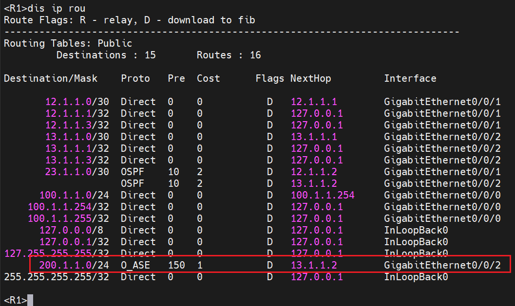
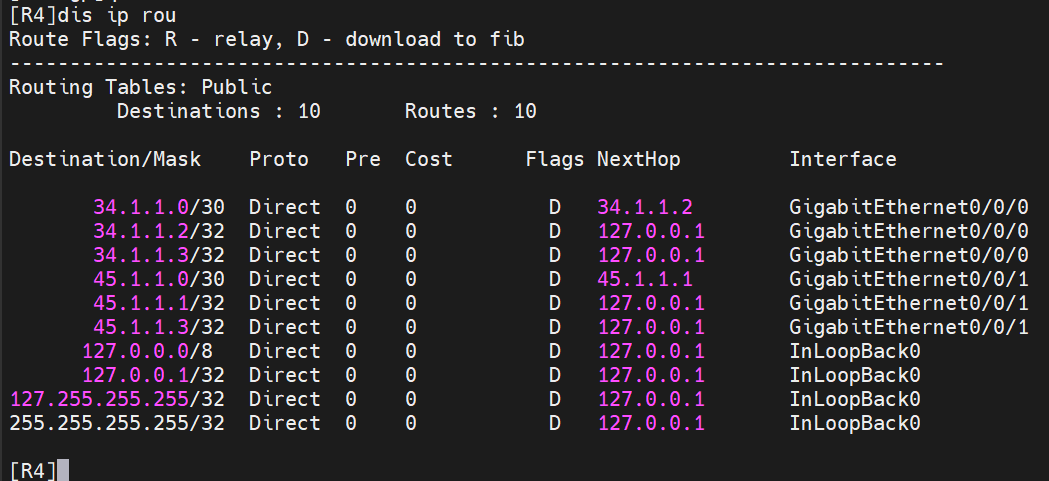
但是我们pc1要ping到pc2,pc2的网关R5没有100的路由啊,是ping不了的
1 | dis ip rou |
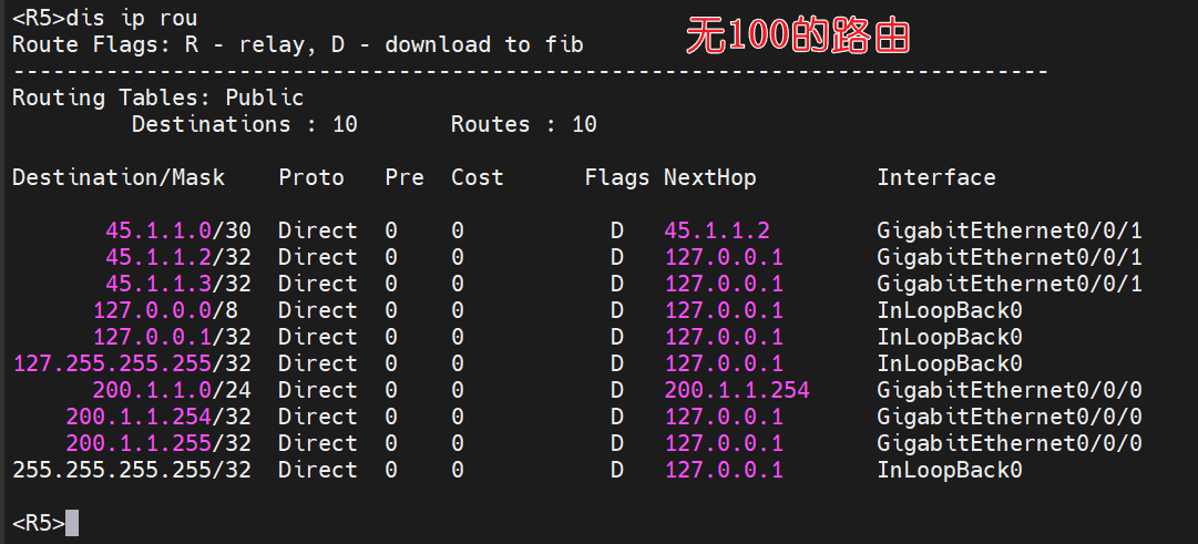
所以我们要在R3上,将ospf 进程1的路由引入到bgp里
1 | sys |
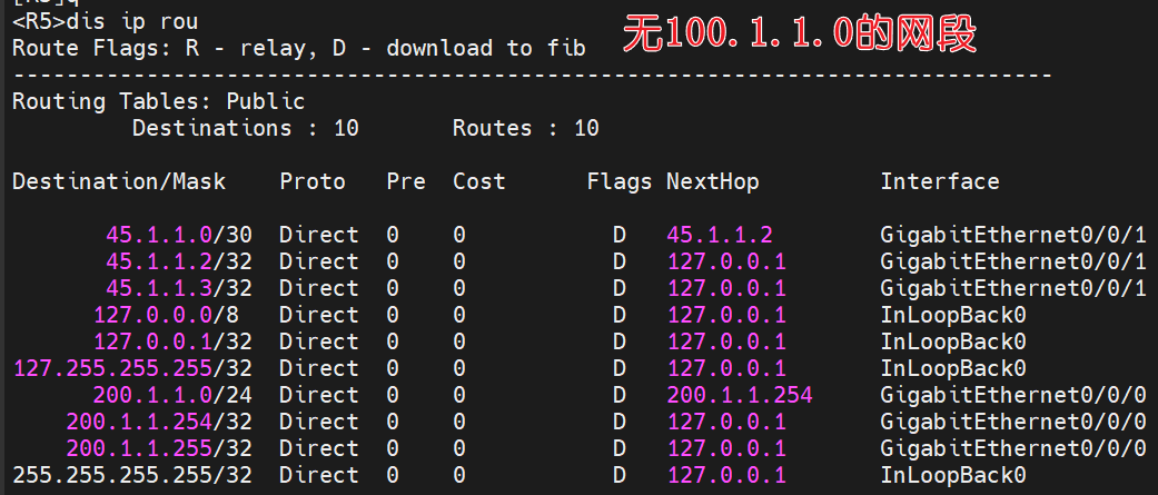
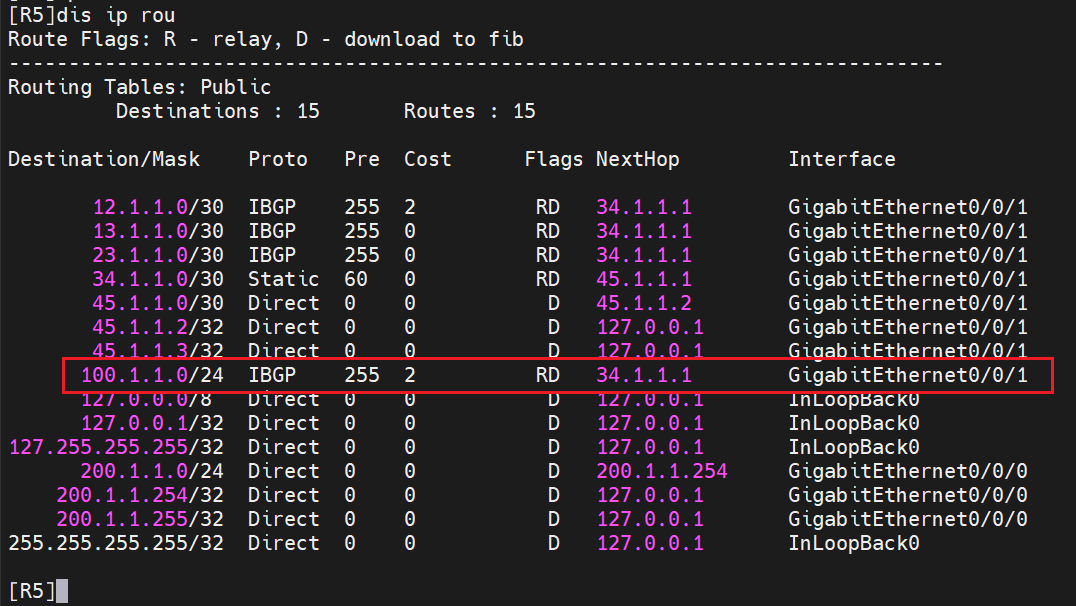
查看R4,R5的路由表,发现下一跳不可达到,就没办法加入到R5的路由表
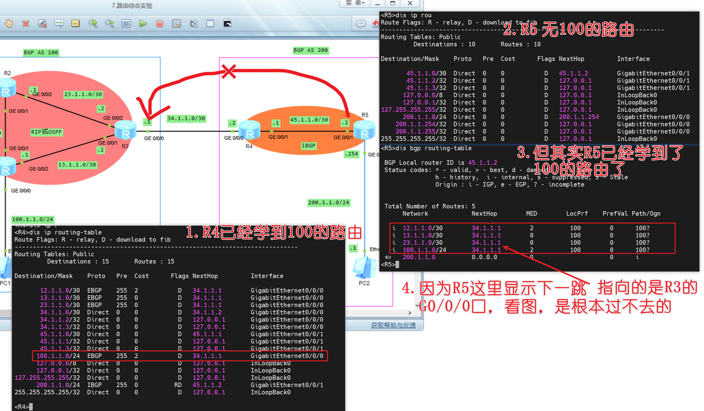
这时候有两个办法,一个是配置R5配置静态路由指向34.1.1.0网段或者R4在bgp里设置R5的下一跳为45.1.1.2口
第一种R5
1 | ip route-static 34.1.1.0 30 45.1.1.1 |
这时候就能学到100的路由了
第二种R4
R5删除静态路由
1 | undo ip route-static 34.1.1.0 30 45.1.1.1 |
R4
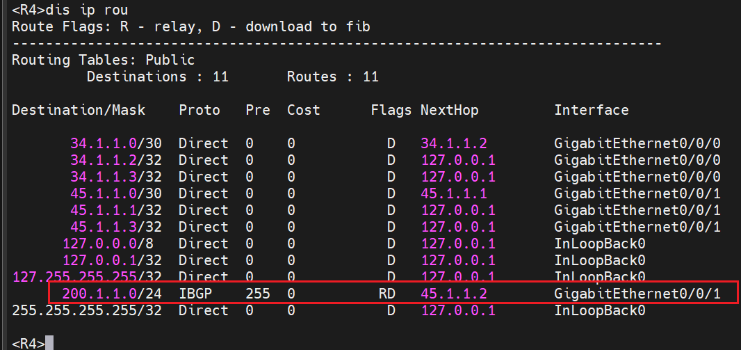
1 | bgp 200 |
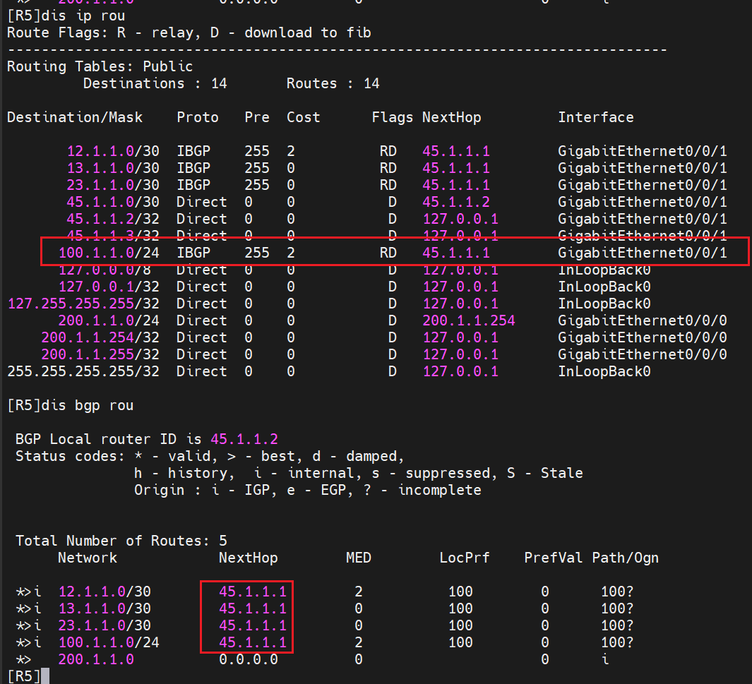
这时候R5已经学到100的路由了
这里就有个疑问,为什么我配置的是啥45.1.1.2为下一跳,而表里显示的45.1.1.1
因为45.1.1.2指的是R4这个IBGP里的bgp对等体,就是直接把45.1.1.2当做了R4,经过R4配置了peer 45.1.1.2 next-hop-local那么R4在把自己学到的ospf里路由通告给R5时,会把R5里的下一跳改成自己R4接口(45.1.1.1)
验证pc互通
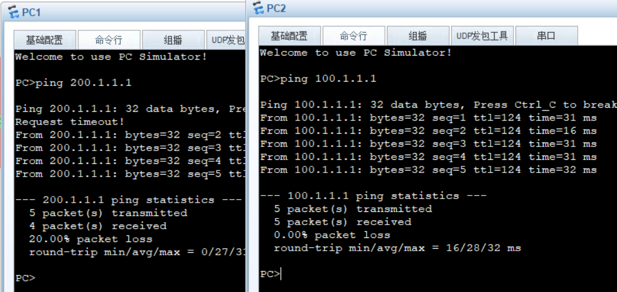
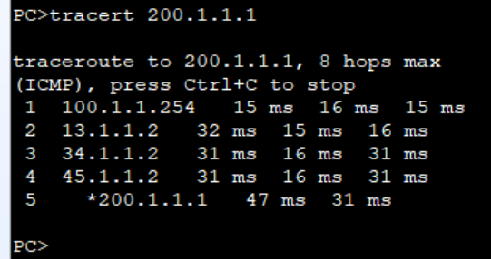
当我们对R1的g0/0/2进行断开之后
R1
1 | sys |
这时候就会多了两条路径,就是走的是R2
实验成功
综合实验[DHCP NAT BFD 策略路由等]
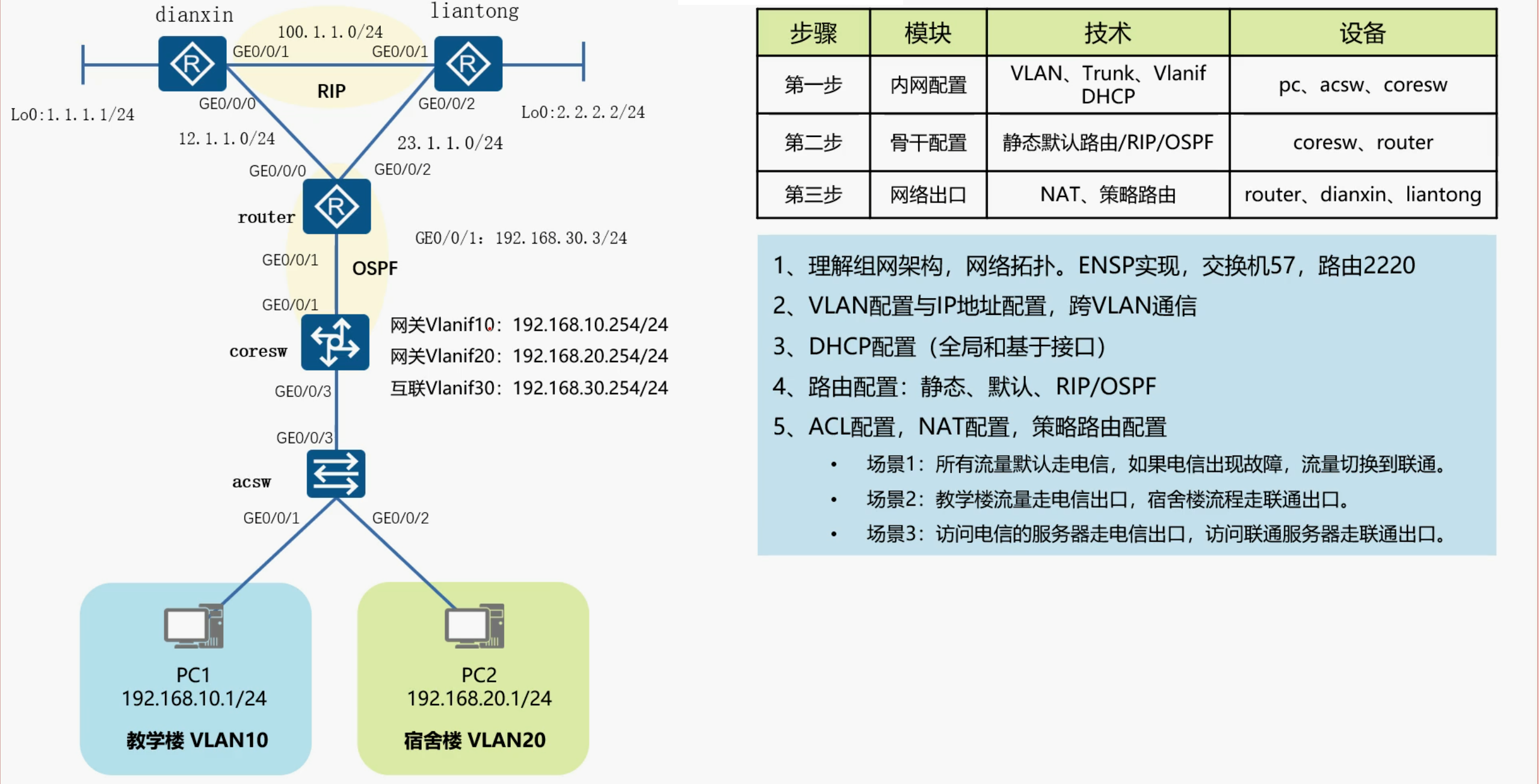
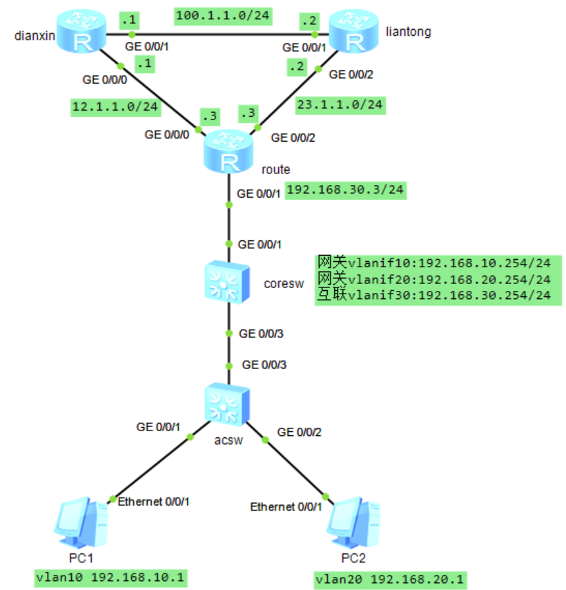
配置IP地址和vlan,dhcp
acsw
1 | system-view |
coresw
1 | system-view |
coresw
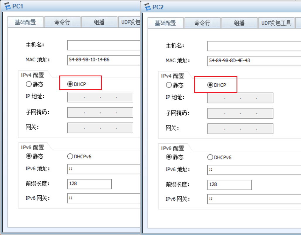
配置dhcp服务器
排除192.168.10.2-192.168.10.253,因为我们pc1只有一台嘛,我们只想让他分配一个地址
1 | dhcp enable |
也能互通
pc1 ping pc2的过程
1.首先判断是否在同一网段
很明显不在同一网段,那么acsw就会把路由交给网关(核心交换机coresw)
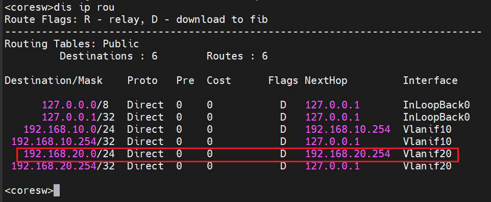
2.那么核心交换机就会查自己的路由表,发现有目的网段,就会把流量转发过去
route
1 | system-view |
dianxin
1 | system-view |
liantong
1 | system-view |
配置静态路由或动态路由(三选一)
背景
此时测试pc1 ping route
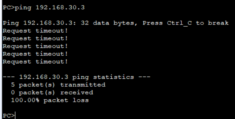
因为流量虽然能到route但是没有返程路由,就ping不通
以下有三种方法三选一
静态路由
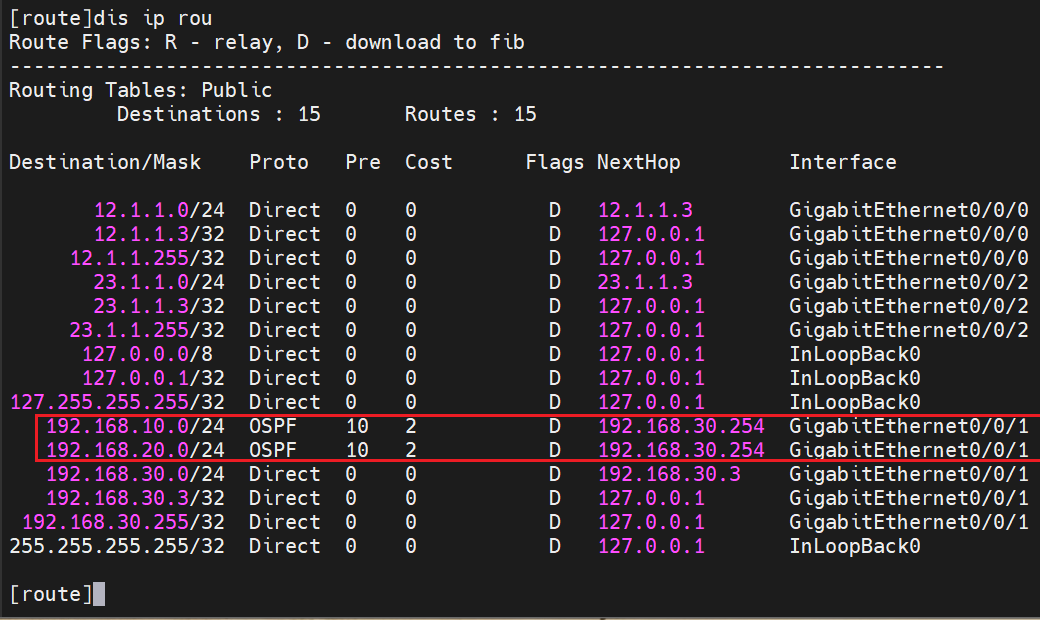
这时候要配置静态ip指向10网段的路由,下一跳是192.168.30.254
route
1 | ip route-static 192.168.10.0 24 192.168.30.254 |
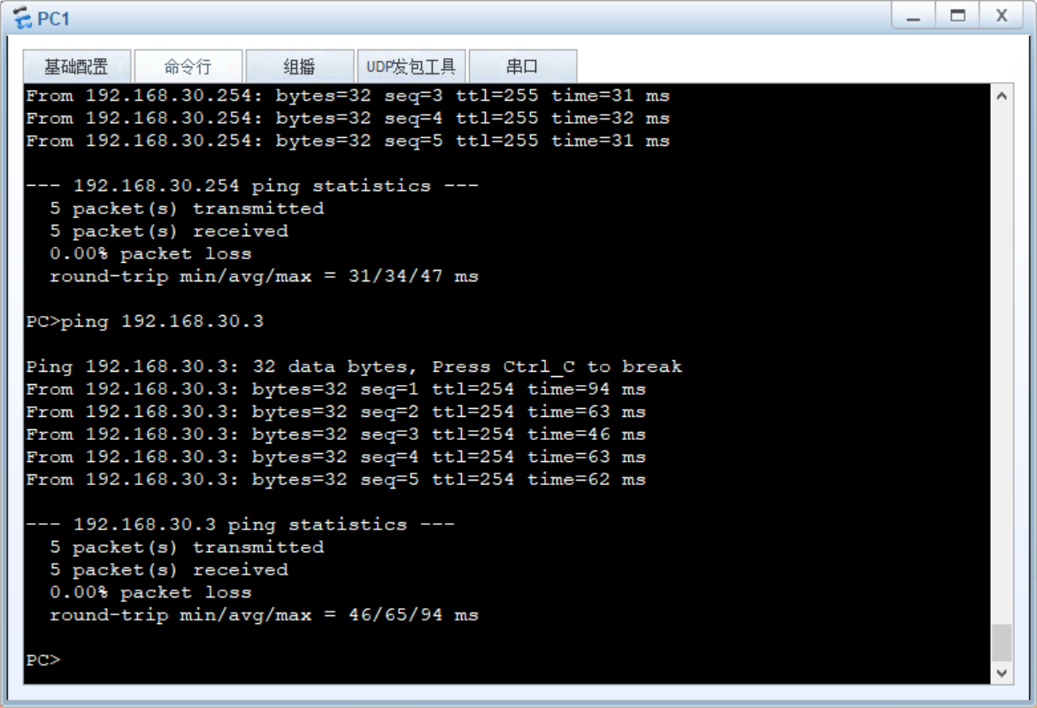
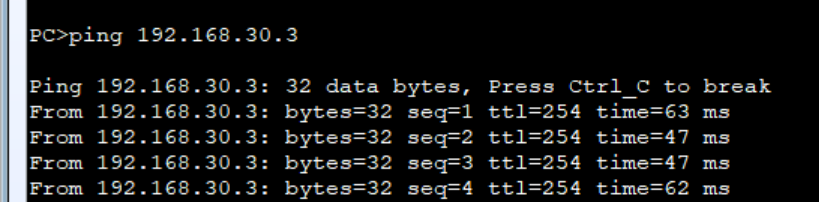
pc1能ping通route了
这是pc2也不能ping了
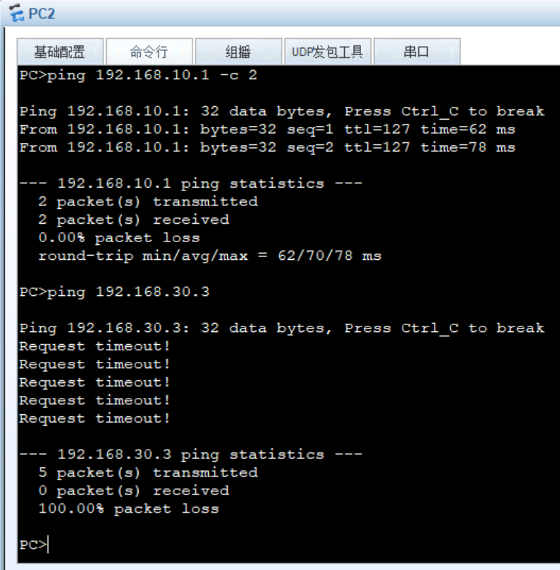
这时候也要配一个静态路由指向20的网段
1 | ip route-static 192.168.20.0 24 192.168.30.254 |
配置Rip
route
1 | rip 1 |
coresw
1 | rip 1 |
这时候route通过coresw宣告的路由学习到了10和20到网段里
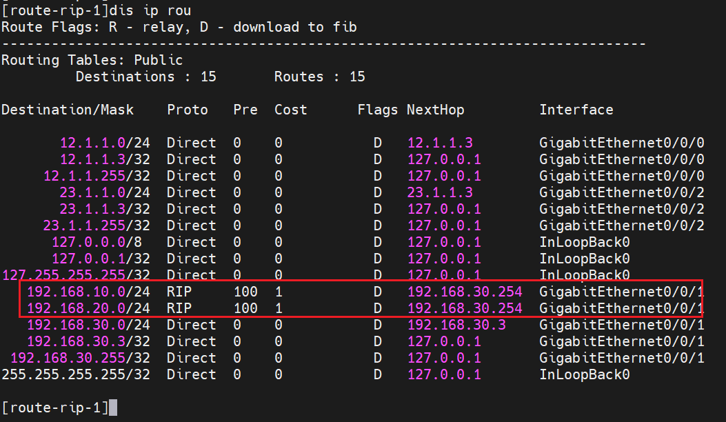
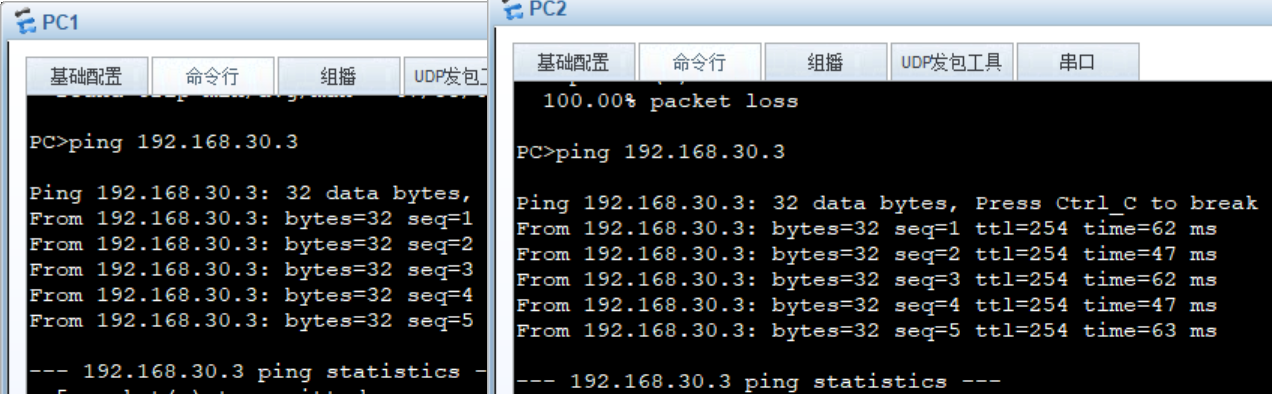
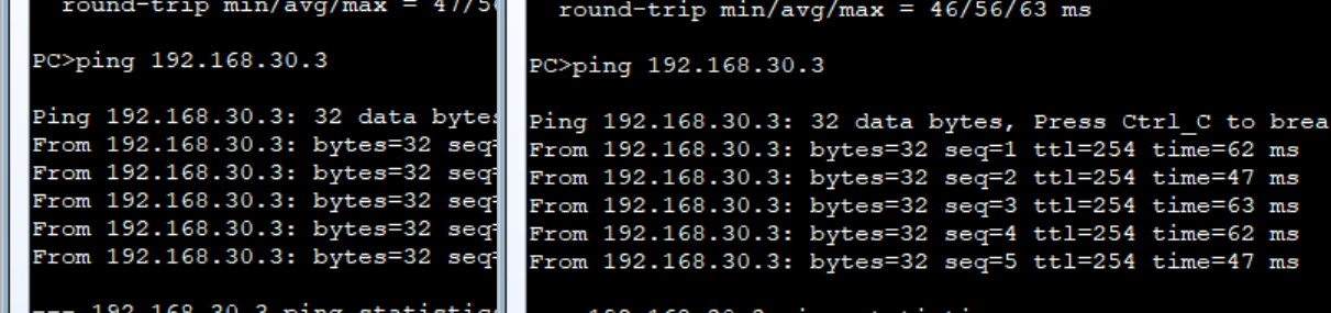
两个都能ping通
配置ospf
route
1 | sys |
coresw
1 | sys |
现在二者已经构建了领居关系
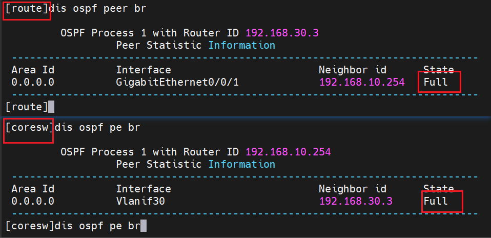
这时候route已经通过ospf学习到了路由
配置运营商之间的动态路由
电信路由器和联通路由器配置环回口,相当于,各种接了一台服务器
dianxin
1 | sys |
liantong
1 | sys |
由于我们在测试,dianxin和liantong的路由器里的其他路由,如果互ping肯定是不通的,现实环境下,两个肯定互通,因为可能运行着bgp等协议,我们这里测试,我们就配一个动态路由,让彼此学习到各自的路由就行了,可以选择rip,ospf,bgp
配置RIP
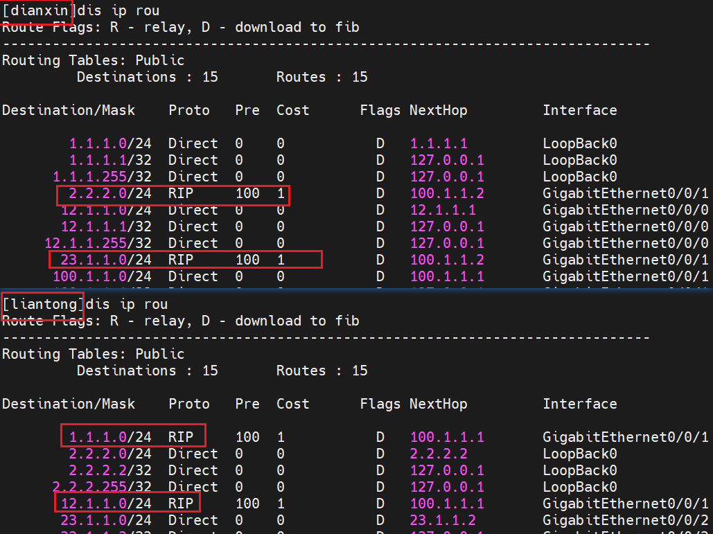
dianxin 由于是a类地址,只能宣告a类网段,这是rip的规则,我前面一个实验也有说过
1 | rip 1 |
liantong
1 | rip 1 |
各自都学到了自己的路由
配置nat
在出口路由器配置nat的easyip
route
1 | sys |
这时候我们去跟踪路由信息,pc ping 电信的1.1.1.1环回口
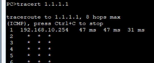
发现他只能到网关,因为网关的路由表里没有目的1.1.1.1的路由,到了网关这里无路可走,就会丢弃,但是我们要让他可走,就要把流量丢给他的老大也就是出口路由器
一般我们在生产中会在网关配置默认路由到出口路由器的
coresw
1 | ip route-static 0.0.0.0 0 192.168.30.3 |
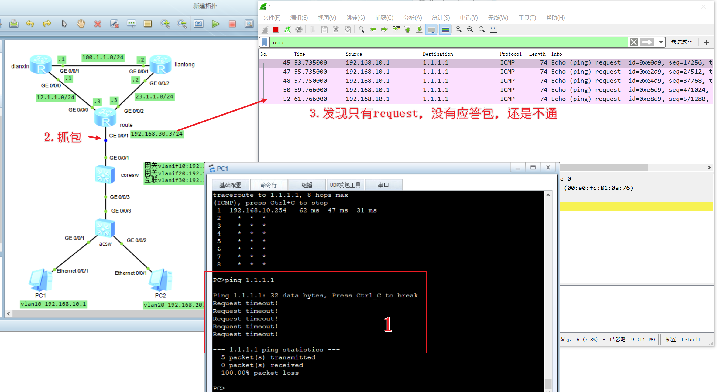
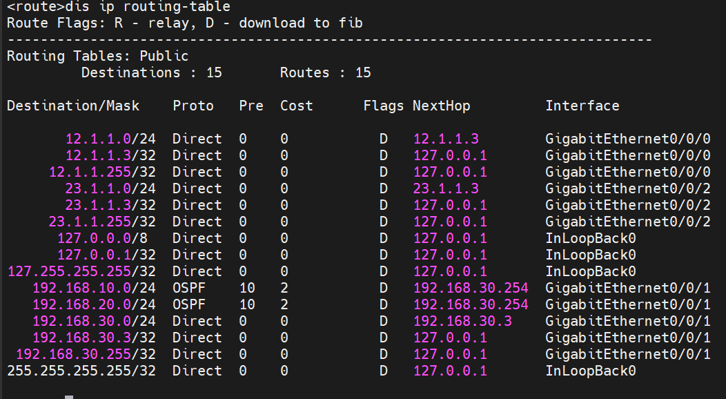
配置了不通,但是至少,我们的流量已经到了出口路由器了,但是出口路由器的路由表也没有目的1.1.1.1的路由
考试重点:在出口路由器都要配置默认路由指向运营商的
这时候我们回顾一下,这里的场景一,默认走电信,出故障走联通
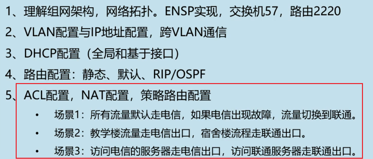
配置场景1
所以我们要配置两个静态路由,则设置电信的优先级最小,因为越小越优先,普通的默认路由优先级是60
route
1 | #指向电信的默认路由,设置低于60的优先级 |
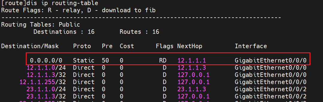
这里只有一条,当这条指向电信的默认路由故障了,才会走向联通,但是还要配置bfd去进行监测才能实现故障转移
配置BFD
dianxin和route配置bfd检测对端接口活动情况
route
1 | undo ip route-static 0.0.0.0 0 12.1.1.1 |
dianxin
1 | bfd |
等待几秒建立连接
1 | dis bfd session all |
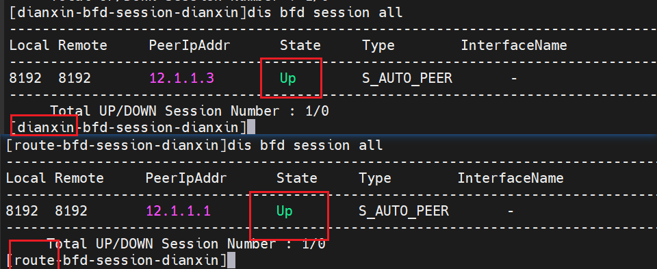
route配置bfd策略
如果 BFD 检测到链路故障下一跳12.1.1.1不可达,这条静态路由会自动从路由表中移除,从而避免流量被错误转发。
1 | ip route-static 0.0.0.0 0 12.1.1.1 preference 50 track bfd-session dianxin |
模拟一下12.1.1.1 down状态
dianxin
1 | int g0/0/0 |
route
1 | dis ip rou |
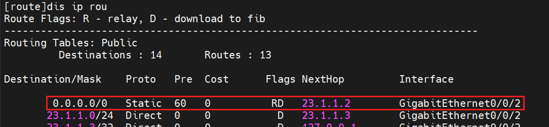
这时候走向电信的默认路由因为出现故障而被bfd自动删除,取而代之的就是走向联通的路由
配置场景2
教学楼流量走电信出口,宿舍楼流程走联通出口。
做这个要删掉前面配置的静态路由哦,每个场景都是独立的
route
1 | undo ip route-static 0.0.0.0 0 12.1.1.1 |
配置acl,匹配流量
以下都在出口路由器配置
1 | acl 2010 |
流分类
分类出两个流量,一个是教学的一个是宿舍的,每个流量应用相应的acl
1 | traffic classifier jiaoxue |
流行为
创建两种种行为,重定向电信的下一跳是12.1.1.1,重定向联通的下一跳是23.1.1.2
1 | traffic behavior re-dianxin |
流策略
我们要将流行为和流策略绑定在一起
1 | traffic policy p |
入接口应用策略路由
1 | interface GigabitEthernet 0/0/1 |
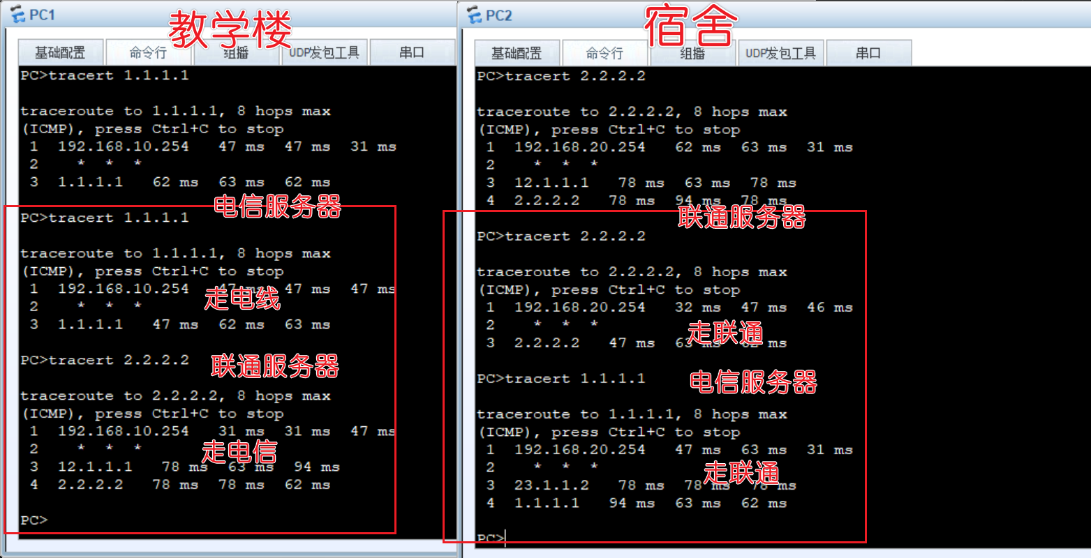
总结一下流量过程,假设我们是教学楼,我们去ping电信服务器1.1.1.1时,流量到了出口路由器的入接口,那么经过流分类中的教学里的acl识别到是教学楼10网段的流量,就成功匹配,然后进行流行为,重定向流量到dianxin,下一跳指向12.1.1.1(电信接口)。其他流量也一样
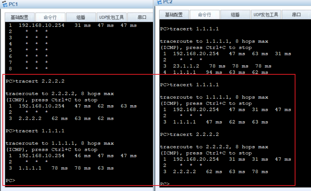
配置场景3
访问电信的服务器走电信出口,访问联通服务器走联通出口。
route
删除前面的配置
1 | interface GigabitEthernet 0/0/1 |
就其实和前面那个场景是差不多,唯一不同的是在acl我们只需要定义目的地址是联通或者电信的就行了,源流量设置为any,这样教学楼和宿舍不管源地址是啥,只要ping哪个服务器,就会被带到哪个路由器
1 | acl 3010 |
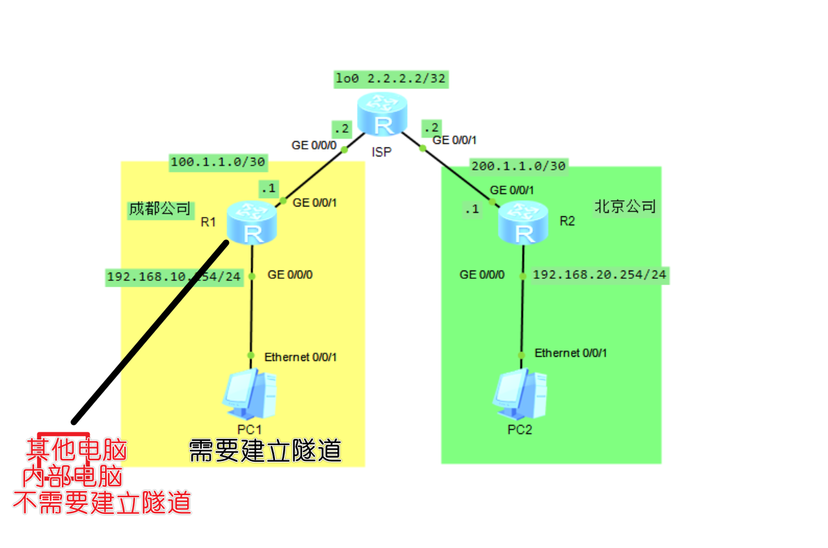
IPsec实验
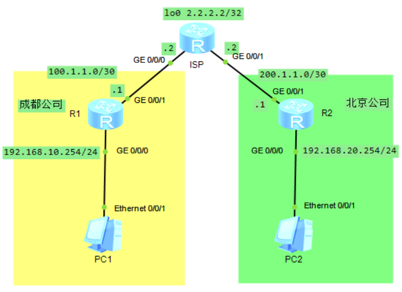

看着上面的表配,这里就不说了
配置静态路由和NAT
一般出口路由器都要配置一条默认路由指向运营商
R1
1 | sys |
R2
1 | sys |
可以ping通互联网,但是不能互通pc,这时候我们要通过配置ipsec把这两个内网打通
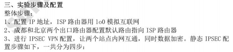
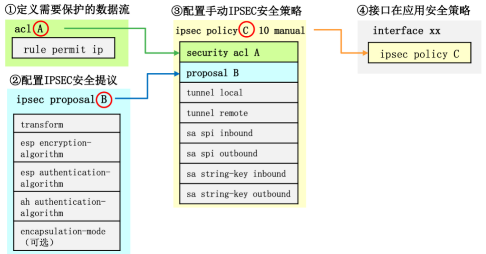
手动配置ipsec
配置acl
定义需要保护的数据流,那条路的路由需要保护,就圈起来
R1
1 | sys |
R2
1 | sys |
配置ipsec提议
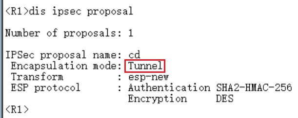
对你即将要建立的隧道,设置认证和加密算法,采用什么算法和方式进行保护,一般默认都是隧道模式,加密用的是加密算法
R1
ipsec提议名字cd(成都)
认证算法采用sha2-256
加密算法采用des
1 | ipsec proposal cd |
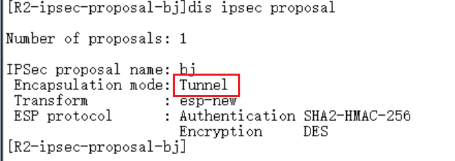
R2
1 | ipsec prpoosal bj |
配置ipsec手动安全策略

这里涉及两个SA编号,在R1的角度上入方向是54321,出方向是12345
那到了R2,你就不能按照R1的来了,你要反着写,入方向是12345,出方向是54321。
都是反着来,一一对应的,千万别搞错
R1
1 | sys |
//配置IPSEC策略chegndu,方式为手动
//包含acl3000的流量
//采用ipsec 提议 cd
//配置隧道本地地址100.1.1.1
//配置隧道远端地址 200.1.1.1
//配置入方向SA编号54321
//配置入方向SA的认证密钥为qianyios
//配置出方向SA编号12345
//配置出方向SA的认证密钥为qianyios
R2
1 | sys |
//配置IPSEC策略beijing,方式为手动
//包含acl3000的流量
//采用ipsec 提议 bj
//配置隧道本地地址 200.1.1.1
//配置隧道远端地址 100.1.1.1
//配置入方向SA编号12345
//配置入方向SA的认证密钥为qianyios
//配置出方向SA编号54321
//配置出方向SA的认证密钥为qianyios
在接口上应用
R1
1 | sys |
R2
1 | sys |
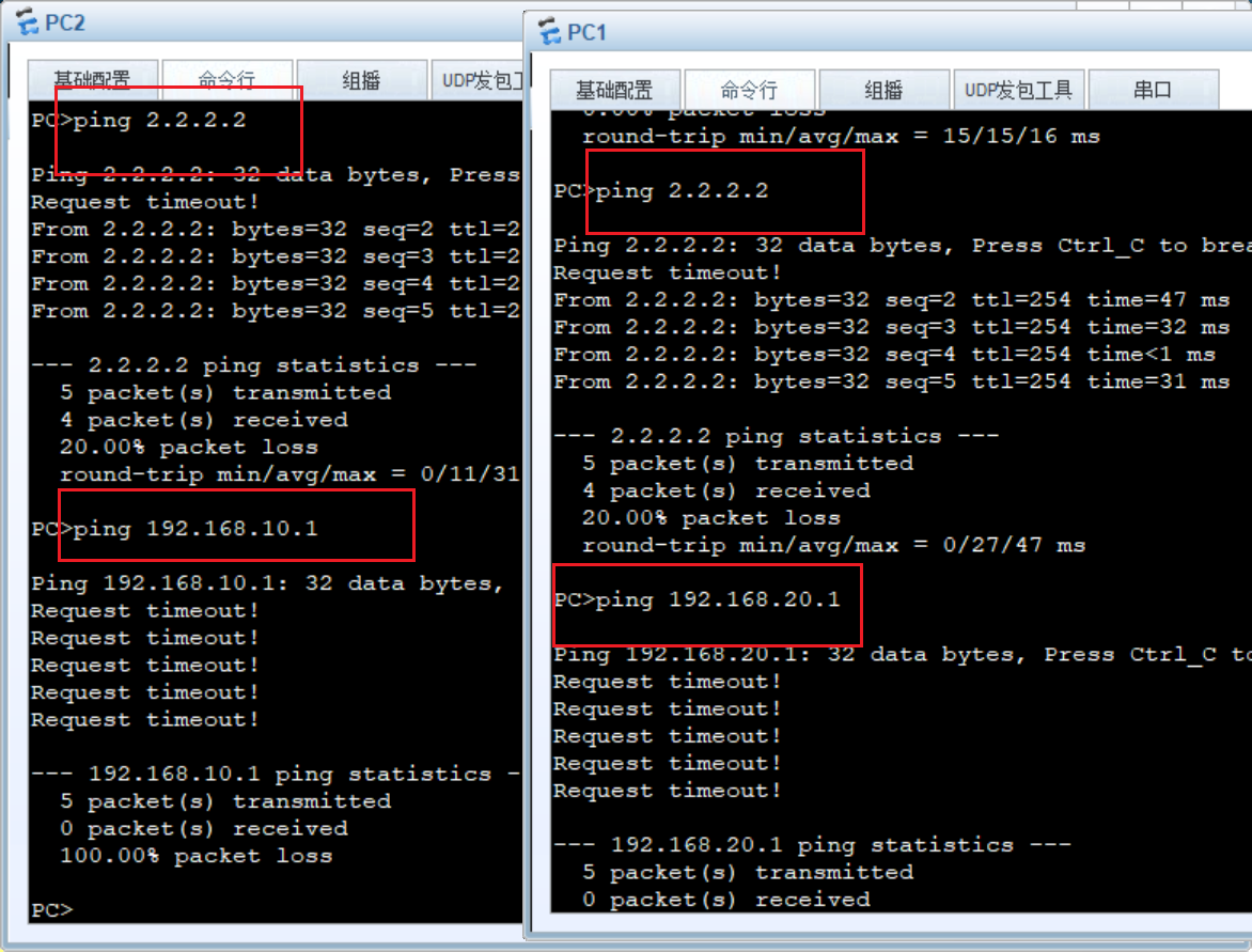
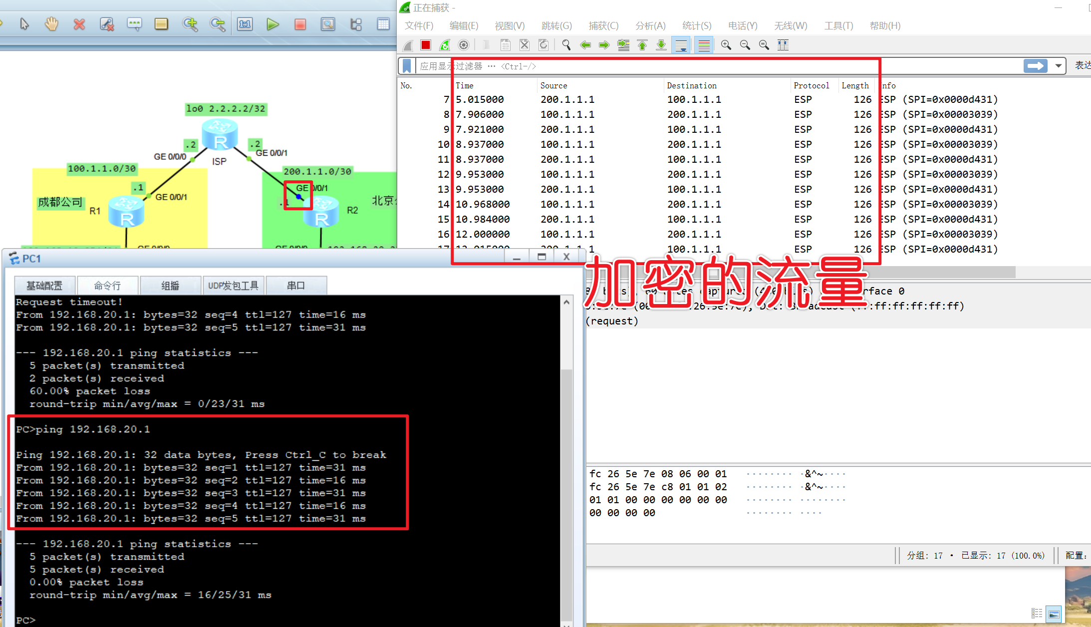
隧道已经建立了,去测试主机是否互通
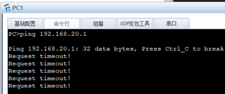
发现不行
问题分析:R1上配置了ACL2000和ACL3000,其中ACL2000用于匹配内部需要NAT的地址,ACL3000用于匹配需要通过VPN隧道加密的流量,两条ACL重合,即ACL2000 会把需要进行 VPN 传递的流量匹配出来,进行 NAT。
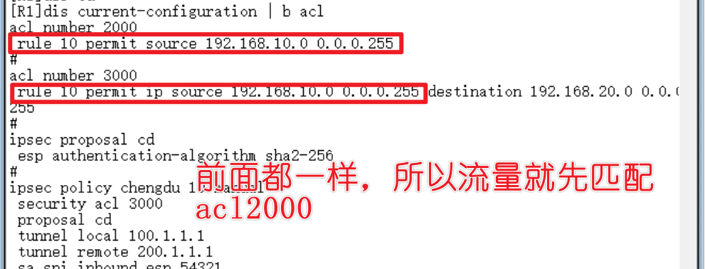
我们不可能说所有电脑都要建立隧道,只有部分电脑是需要建立隧道的,acl2000在前期本身就是给所有内部流量去做nat转换的这其中就包括要建立隧道的pc1流量,那我们就应该重新做acl,换成高级acl 3001来做nat转换,就是在acl 3001,把需要建立隧道的流量设置成deny,其他流量运行通过,应用在nat转换就好了,这样子就不会匹配他了,就可以匹配acl3000做隧道转换了,这个理论在R2也要重新推翻acl 2000去重做acl 3001
R1
1 | sys |
acl 3001就是禁止192.168.10.0到192.168.20.0到流量,接着匹配其他ip允许通过,然后应用在出口路由器的nat转换
在R2也是一样的道理,删掉acl 2000,重做acl 3001
R2
1 | sys |
已经可以互通了
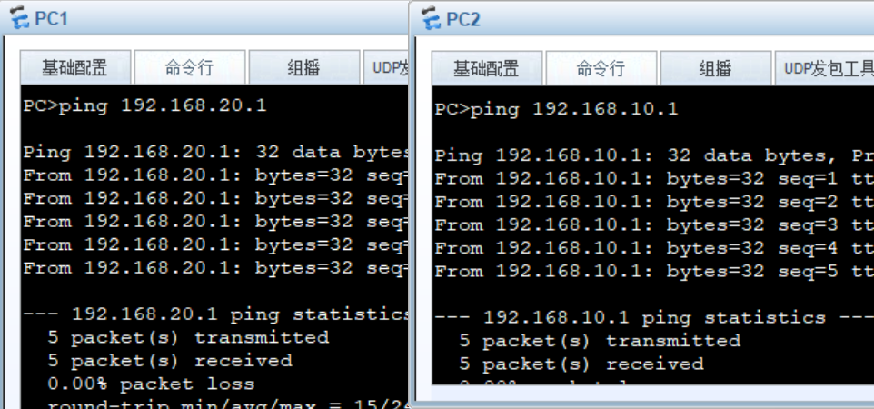
手动配置ipsec成功
防火墙配置
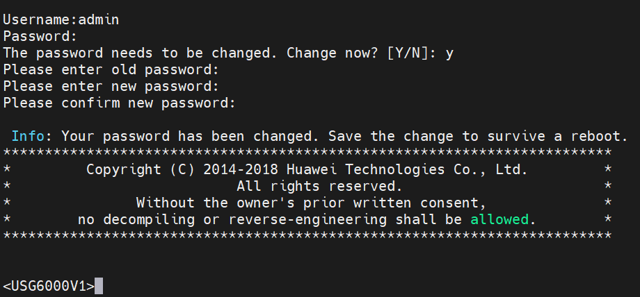
这里的防火墙用的是USG6000V,首次运行需要防火墙导入包,要下载一个vdi下载地址,下载完导入即可
这里首先要输入的默认用户名:admin
然后回车,再输入默认密码:Admin@123
再回车,会询问你是否要修改密码,输入“y”表示yes
再回车,先输入一遍旧密码
再回车,输入新密码 qianyios@123
再回车,再输入一次新密码
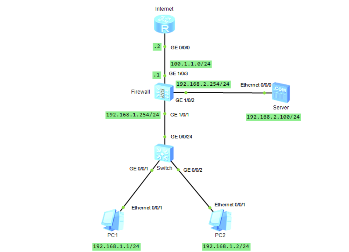
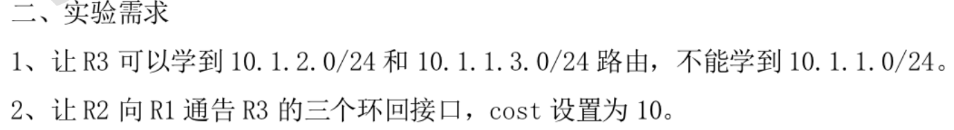
配置要求
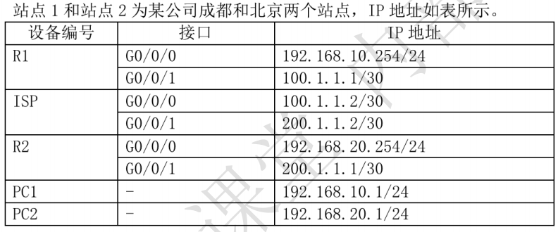
(1)防火墙接口的 IP地址如拓扑所示,将接口划入相应的安全区域。
(2)内网主机PC1可以主动访问Internet,但Internet无法主动访问PC1。
(3)出口防火墙进行NAT,NAT 公网地址池 100.1.1.10-100.1.1.20。
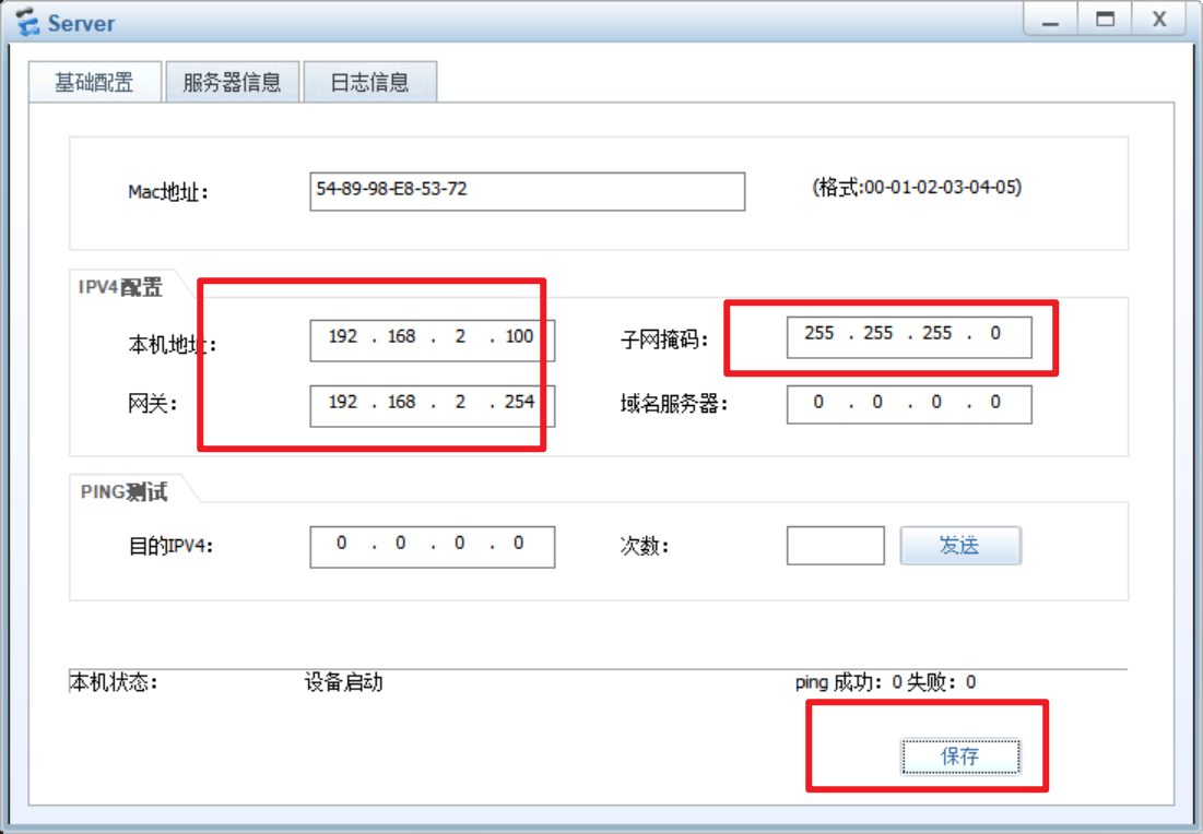
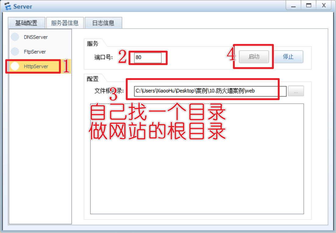
(4)Internet 可以通过公网地址100.1.1.100/24访问目的地址为 192.168.2.100/24的内部 Web 服务。
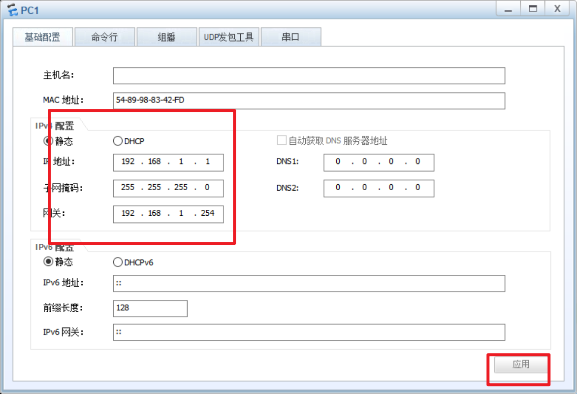
配置IP地址
本次实验就只用pc1做实验,都一样的,pc2就配置ip地址了
Internet
1 | sys |
Firewalld
前面的配置防火墙密码登入之后,再进行下面的操作
1 | sys |
防火墙安全域
firewalld
把接口加入到相应的区域去
1 | sys |
安全策略的配置
firewalld
1 | sys |
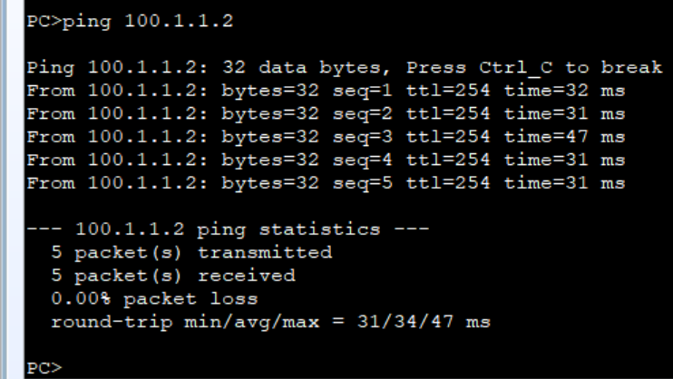
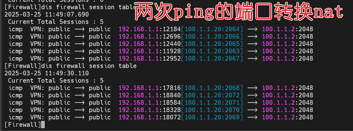
做完之后,pc1是无法访问互联网的,因为出口没有做NAT,开启端口转换
1 | nat address-group natgroup1 |
pc1成功访问互联网
配置pc访问dmz
firewall
配置trust流量运行访问dmz区域,也就是服务器区域
1 | sys |
配置端口映射
firewall
把内网web服务映射到公网地址
1 | sys |
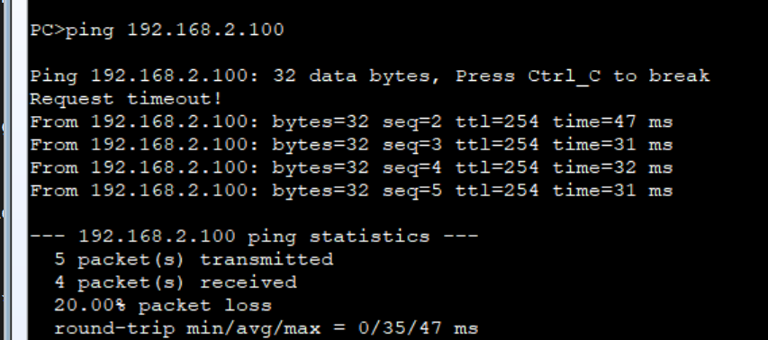
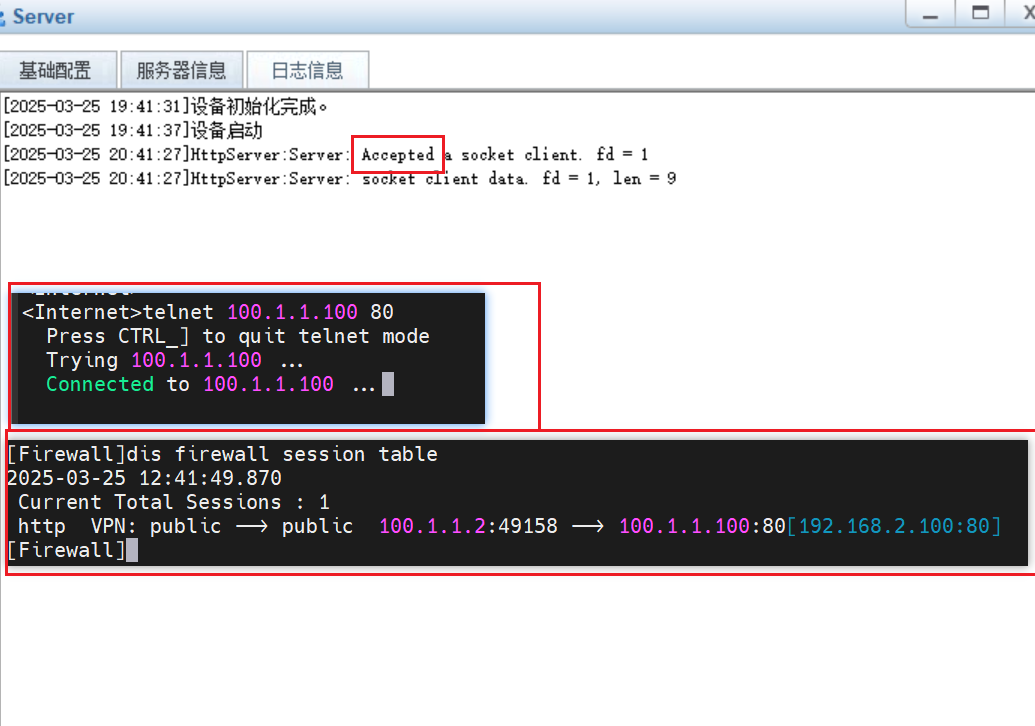
这时候测试internet通过公网100.1.1.100:80去访问服务器的80端口
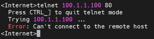
不行,因为untrust没有放行流量到dmz区域
1 | sys |
路由策略
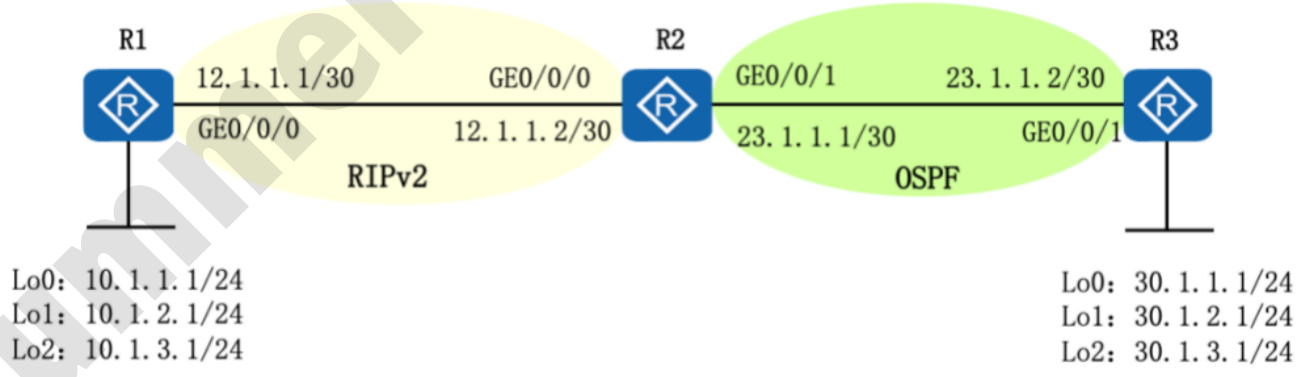
配置ip地址
R1
1 | sys |
R2
1 | sys |
R3
1 | sys |
配置RIP和OSPF
R1
1 | rip 1 |
R2
1 | rip 1 |
R3
1 | ospf 1 |
在R2上查看路由表,已经通过RIP和OSPF分别学到了3条路由
1 | dis ip rou |
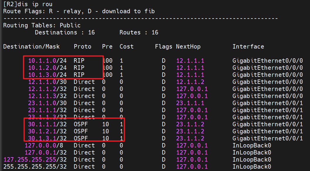
配置路由引入和路由策略以及设置开销
R2
1 | acl 2000 |
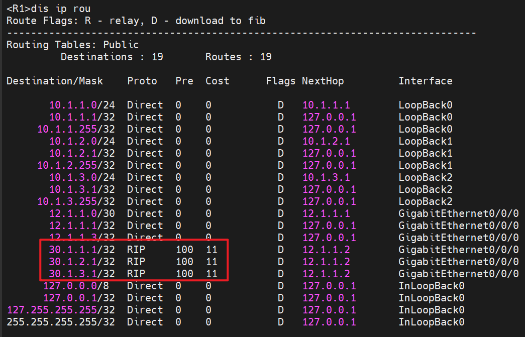
R1上查看从何R2学到的rip路由,开销是11,也就是前面在R2引入ospf的路由,本身开销是10,而R2本身算一跳,所以开销就是11
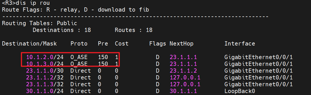
R2上配置路由引入和路由策略,进行路由过滤
1 | acl 2001 |
R3上查看路由学习情况,通过路由策略过滤,R3只学到了10.1.2.0/24和10.1.3.0/24,没有学到 10.1.1.0/24,实验成功!
难免会有出错的地方
如果细心的你发现了小失误,可以在下方评论区告诉我,或者私信我!
非常感谢大家的热烈支持!
 微信
微信 支付宝
支付宝